Kia Picanto (JA): Engine Control / Fuel System / Engine Control System
Components and components location
| Components Location |

| 1. ECM (Engine Control Module) 2. Manifold Absolute Pressure Sensor (MAPS) 3. Intake Air Temperature Sensor (IATS) 4. Boost Pressure Sensor (BPS) 5. Engine Coolant Temperature Sensor (ECTS) 6. Throttle Position Sensor (TPS) [integrated into ETC Module] 7. Crankshaft Position Sensor (CKPS) 8. Camshaft Position Sensor (CMPS) [Bank 1 / Intake] 9. Camshaft Position Sensor (CMPS) [Bank 1 / Exhaust] 10. Knock Sensor (KS) 11. Heated Oxygen Sensor (HO2S) [Bank 1 / Sensor 1] 12. Heated Oxygen Sensor (HO2S) [Bank 1 / Sensor 2] 13. Exhaust Gas Temperature Sensor (EGTS) #1 14. Exhaust Gas Temperature Sensor (EGTS) #2 15. Rail Pressure Sensor (RPS) 16. Accelerator Position Sensor (APS) | 17. A/C Pressure Transducer (APT) 18. Fuel level sender (FLS) 19. Ambient Temperature Sensor (ATS) 20. ETC Motor [integrated into ETC Module] 21. Injector 22. Purge Control Solenoid Valve (PCSV) 23. CVVT Oil Control Valve (OCV) [Bank 1 / Intake] 24. CVVT Oil Control Valve (OCV) [Bank 1 / Exhaust] 25. Fuel Pressure Control Valve (FPCV) 26. Electric Waste Gate Actuator (EWGA) 27. RCV Control Solenoid Valve 28. Ignition Coil 29. Main Relay 30. Fuel Pump Relay 31. Data Link Connector (DLC) [16 Pin] 32. Multi-Purpose Check Connector [6 Pin] |
| 1. ECM (Engine Control Module) | 2. Manifold Absolute Pressure Sensor (MAPS) 3. Intake Air Temperature Sensor (IATS) |
|
|
| 4. Boost Pressure Sensor (BPS) | 5. Engine Coolant Temperature Sensor (ECTS) |
|
|
| 6. Throttle Position Sensor (TPS) [integrated into ETC Module] 20. ETC Motor [integrated into ETC Module] | 7. Crankshaft Position Sensor (CKPS) |
|
|
| 8. Camshaft Position Sensor (CMPS) [Bank 1 / Intake] | 9. Camshaft Position Sensor (CMPS) [Bank 1 / Exhaust] |
|
|
| 10. Knock Sensor (KS) | 11. Heated Oxygen Sensor (HO2S) [Bank 1 / Sensor 1] |
|
|
| 12. Heated Oxygen Sensor (HO2S) [Bank 1 / Sensor 2] | 13. Exhaust Gas Temperature Sensor (EGTS) #1 |
|
|
| 14. Exhaust Gas Temperature Sensor (EGTS) #2 | 15. Rail Pressure Sensor (RPS) |
|
|
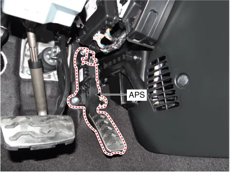
| 16. Accelerator Position Sensor (APS) | 17. A/C Pressure Transducer (APT) |
|
|
| 18. Fuel level sender (FLS) | 19. Ambient Temperature Sensor (ATS) |
|
|
| 21. Injector | 22. Purge Control Solenoid Valve (PCSV) |
|
|
| 23. CVVT Oil Control Valve (OCV) [Bank 1 / Intake] | 24. CVVT Oil Control Valve (OCV) [Bank 1 / Exhaust] |
|
|
| 25. Fuel Pressure Control Valve (FPCV) | 26. Electric Waste Gate Actuator (EWGA) |
|
|
| 27. RCV Control Solenoid Valve | 28. Ignition Coil |
|
|
| 29. Main Relay 30. Fuel Pump Relay | 31. Data Link Connector (DLC) [16 Pin] |
|
|
| 32. Multi-Purpose Check Connector [6 Pin] | |
|


Description and operation
| Description |
| 1. | Engine is hard to start or does not start at all. |
| 2. | Unstable idle. |
| 3. | Poor driveability |
|

| • | Catalyst |
| • | Fuel system |
| • | Manifold Absolute Pressure Sensor (MAPS) |
| • | Intake air temperature sensor |
| • | Engine coolant temperature sensor |
| • | ETC module (TPS & ETC motor) |
| • | Heated oxygen sensor (Upstream) |
| • | Heated oxygen sensor heater (Upstream) |
| • | Heated oxygen sensor (Downstream) |
| • | Heated oxygen sensor heater (Downstream) |
| • | Injector |
| • | Misfire |
| • | Crankshaft position sensor |
| • | Camshaft position sensor |
| • | Evaporative emission control system |
| • | Vehicle speed sensor |
| • | Power supply |
| • | ECM/ PCM |
| • | MT encoding |
| • | Acceleration sensor |
| • | MIL-ON request signal |
| • | Power stage |
Refer to "Inspection Chart For Diagnostic Trouble Codes (DTC)" for more information. |
| • | Heated oxygen sensor (HO2S) |
| • | Manifold Absolute Pressure Sensor (MAPS) |
| • | Engine coolant temperature sensor (ECTS) |
| • | ETC module (TPS & ETC motor) |
| • | Injectors |
| • | ECM |
Refer to "Inspection Chart For Diagnostic Trouble Codes (DTC)" for more information. |
| 1. | After turning ON the ignition key, ensure that the light illuminates for about 5 seconds and then goes out. |
| 2. | If the light does not illuminate, check for an open circuit in the harness, a blown fuse or a blown bulb. |
If
a sensor connector is disconnected with the ignition switch turned on,
the diagnostic trouble code (DTC) will be recorded. In this case,
disconnect the battery negative terminal (-) for 15 seconds or more
until the diagnostic memory is erased. |

| 1. | When
the same malfunction is detected and maintained during two consecutive
driving cycles, the MIL will automatically illuminate. |
| 2. | The MIL will go out automatically if no fault is detected for 3 consecutive driving cycles. |
| 3. | A
Diagnostic Trouble Code(DTC) is recorded in ECM memory when a
malfunction is detected during two consecutive driving cycles. The MIL
will illuminate when the malfunction is detected on the second driving
cycle. If a misfire is detected, a DTC will be recorded, and the MIL will illuminate, immediately after a fault is first detected. |
| 4. | A
Diagnostic Trouble Code(DTC) will automatically be erased from ECM
memory if the same malfunction is not detected for 40 driving cycles.
|
- Engine Control Module (ECM)
- ETC (Electronic Throttle Control) System
- Manifold Absolute Pressure Sensor (MAPS)
- Intake Air Temperature Sensor (IATS)
- Ambient Temperature Sensor (ATS)
- Boost Pressure Sensor (BPS)
- Engine Coolant Temperature Sensor (ECTS)
- Crankshaft Position Sensor (CKPS)
- Camshaft Position Sensor (CMPS)
- Knock Sensor (KS)
- Heated Oxygen Sensor (HO2S)
- Exhaust Gas Temperature Sensor (EGTS)
- Rail Pressure Sensor (RPS)
- Accelerator Position Sensor (APS)
- Injector
- Purge Control Solenoid Valve (PCSV)
- CVVT Oil Control Valve (OCV)
- Electric Waste Gate Actuator (EWGA)
- RCV Control Solenoid Valve
- Fuel Pressure Control Valve (FPCV)
Specifications Specifications Fuel Delivery System Items Specification Fuel Tank Capacity 35 L (9.
Schematic diagrams ECM Terminal and Input/Output signal [M/T] 1. Harness Connector 2. Terminal Function [M/T] [Connector A] Pin No Description 1 Ignition coil (Cylinder #3) control output 2 Ignition coil (Cylinder #2) control output 3 - 4 Electric Waste Gate Actuator (EWGA) Motor [+] control output 5 Injector (Cylinder #3) [Low] control output 6 - 7 Engine Coolant Temperature Sensor (ECTS) signal input 8 - 9 Boost Pressure Sensor (BPS) signal input 10 - 11 - 12 Electric Waste Gate Actuator (EWGA) Feed beck signal input 13 Throttle Position Sensor (TPS) 1 signal input 14 Accelerator Position Sensor (APS) 1 signal input 15 Brake Booster Vacuum Pressure Sensor (BBVPS) signal input 16 - 17 Ignition coil (Cylinder #1) control output 18 ETC motor [+] control output 19 Electric Waste Gate Actuator (EWGA) DC Motor [-] control output 20 Injector (Cylinder #2) [Low] control output 21 Wiper switch signal input 22 Neutral Switch signal input 23 - 24 Camshaft Position Sensor (CMPS) [Bank 1/Exhaust] signal input 25 A/C dual pressure switch signal input 26 Vehicle speed signal input 27 Start signal input 28 Brake Test switch signal input 29 Brake Light switch signal input 30 Clutch switch signal input 31 Injector (Cylinder #2) [High] control output 32 Injector (Cylinder #3) [High] control output 33 - 34 Injector (Cylinder #1) [Low] control output 35 Fuel Pressure Control Valve (FPCV) [High] control output 36 Camshaft position sensor (CMPS) [Bank 1/Intake] ground 37 Camshaft position sensor (CMPS) [Bank 1/Exhaust] ground 38 - 39 - 40 - 41 Heated Oxygen Sensor (HO2S) [Bank 1/Sensor 2] signal input 42 - 43 Battery Sensor Temperature signal input 44 ISG OFF switch signal input 45 Electric load signal input [Defrost] 46 - 47 Injector (Cylinder #1) [High] control output 48 ETC motor [-] control output 49 - 50 Fuel Pressure Control Valve (FPCV) [Low] control output 51 Wheel speed sensor [A] signal input 52 Wheel speed sensor [B] signal input 53 Crankshaft Position Sensor (CKPS) ground 54 Crankshaft Position Sensor (CKPS) signal input 55 - 56 Camshaft Position Sensor (CMPS) [Bank 1/Intake] signal input 57 Heated Oxygen Sensor (HO2S) [Bank 1/Sensor 2] ground 58 - 59 Battery Sensor Current Direct signal input 60 - [Connector B] Pin No Description 1 ECM ground 2 ECM ground 3 ECM ground 4 Battery power (B+) 5 Battery power (B+) 6 Battery power (B+) 7 Battery power (B+) 8 Accelerator Position Sensor (APS) #1 ground 9 Manifold Air Temperature Sensor (MAPS) ground 10 Boost Pressure Sensor (BPS) ground 11 - 12 Electric Waste Gate Actuator (EWGA) ground 13 - 14 - 15 - 16 Engine Coolant Temperature Sensor (ECTS) ground 17 - 18 - 19 - 20 A/C compressor relay control output 21 - 22 CVVT Oil Control Valve (OCV) [Bank 1/Intake] control output 23 - 24 Cooling fan PWM control output 25 - 26 - 27 Fuel pump relay control output (With Immobilizer/Smart key) 28 - 29 Ignition switch signal input 30 Accelerator Position Sensor (APS) #2 ground 31 - 32 - 33 Battery sensor ground 34 - 35 - 36 Rail Pressure Sensor (RPS) ground 37 - 38 - 39 - 40 - 41 Start relay [Low] control output 42 - 43 Accelerator Position Sensor (APS) #2 power (+5V) 44 Camshaft Position Sensor (CMPS) power (+5V) 45 - 46 ISG OFF lamp signal output 47 - 48 - 49 - 50 CVVT Oil Control Valve (OCV) [Bank 1/Exhaust] control output 51 Main relay control output 52 Throttle Position Sensor (TPS) ground 53 Blower Switch MAX.
Other information:
Kia Picanto (JA) 2017-2026 Service & Repair Manual: Headlamp Leveling Actuator
Components and components location Components Repair procedures Removal 1.Disconnect the negative (-) battery terminal. 2.Remove the headlamp assembly. (Refer to Lighting System - "Headlamps") Installation 1.Install the headlamp assembly.
Kia Picanto (JA) 2017-2026 Service & Repair Manual: Heater & A/C Control Unit(Full Automatic)
Components and components location Components Control Panel Connector pin function No. Connector A Connector B 1 Battery PAB IGN1 2 ISG Battery (+) PAB On signal 3 Illumination (+) PAB Off signal 4 Sensor REF (+5V) - 5 Mode control actua
Categories
- Manuals Home
- Kia Picanto Owners Manual
- Kia Picanto Service Manual
- Charging System
- Body Electrical System
- Engine Mechanical System
- New on site
- Most important about car
