Kia Picanto (JA): Cylinder Head Assembly / Cylinder Head
Repair procedures
| Removal |
|

|

| 1. | Remove the engine room under cover.
(Refer to Engine and Transaxle Assembly - "Engine Room Under Cover")
|
| 2. | Drain the coolant.
(Refer to Cooling System - Coolant")
|
| 3. | Remove the intake manifold.
(Refer to Intake and Exhaust System - "Intake Manifold")
|
| 4. | Remove the turbo manifold module.
(Refer to Intake and Exhaust System - "Turbo Manifold Module")
|
| 5. | Remove the water temperature control assembly.
(Refer to Cooling System - "Water Temperature Control Assembly")
|
| 6. | Remove the vacuum pump.
(Refer to Cylinder Head Assembly - "Vacuum Pump")
|
| 7. | Remove the cylinder head cover.
(Refer to Cylinder Head Assembly - "Cylinder Head Cover")
|
| 8. | Remove the delivery pipe.
(Refer to Engine Control / Fuel System - "Delivery Pipe")
|
| 9. | Remove the timing chain.
(Refer to Timing System - “Timing Chain”)
|
| 10. | Remove the camshaft.
(Refer to Cylinder Head Assembly - "Camshaft" )
|
| 11. | Remove the intake and exhaust oil control valve (OCV).
(Refer to Engine Control / Fuel System - "CVVT Oil Control Valve (OCV)")
|
| 12. | Remove the camshaft position sensor (CMPS).
(Refer to Engine Control / Fuel System - "Camshaft Position Sensor (CMPS)")
|
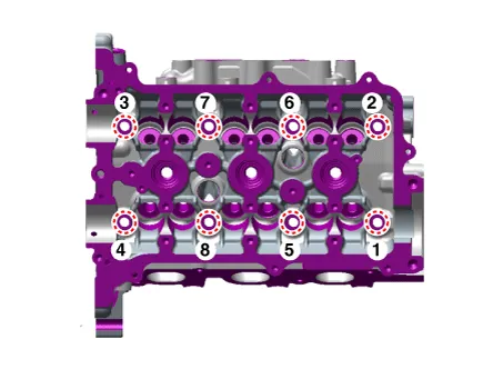
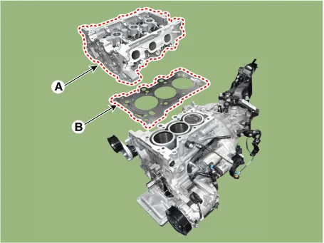
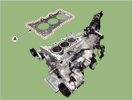
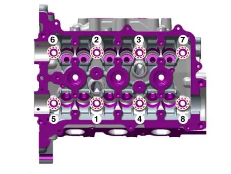
| 13. | Remove the cylinder head.
|
| Disassembly |
Identify
MLA (Mechanical Lash Adjuster), valves, valve springs as they are
removed so that each item can be reinstalled in its original position. |
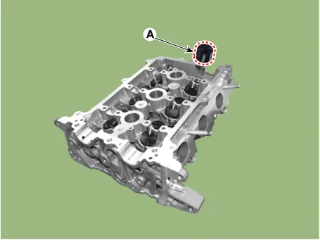
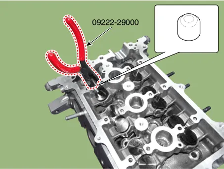
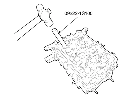
| 1. | Remove the mechanical lash adjusters (MLA) (A).
|
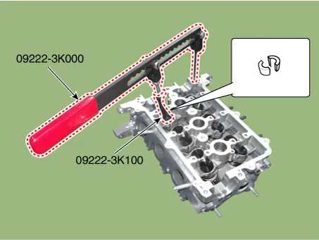
| 2. | Remove the valves.
|
| Inspection |
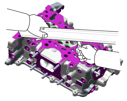
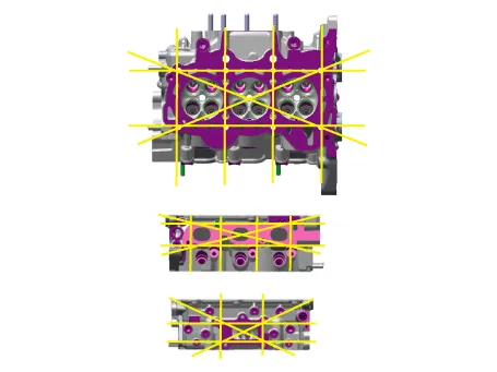
| 1. | Inspect for flatness. Using
a precision straight edge and feeler gauge, measure the surface
contacting cylinder block and inspect the manifolds for warpage. If the flatness is greater than maximum, replace the cylinder head.
|
| 2. | Inspect for cracks. Check
the combustion chamber, intake ports, exhaust ports and cylinder block
surface for cracks. If cracked, replace the cylinder head. |
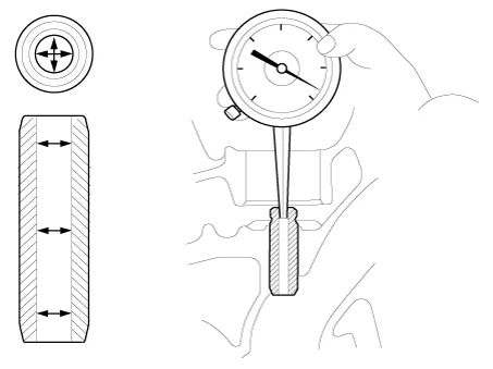
| 1. | Inspect valve stems and valve guides.
|
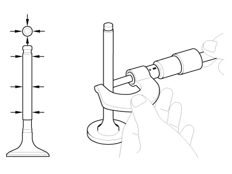
| 2. | Inspect valves.
|
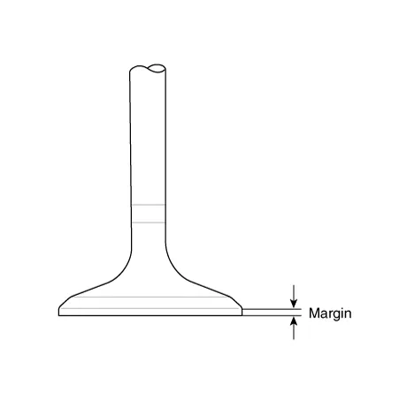
| 3. | Inspect valve seats.
|
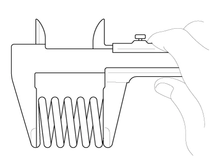
| 4. | Inspect valve springs.
|
| 1. | Inspect the MLA. Using a micrometer, measure the MLA outside diameter.
|
| 2. | Using a caliper gauge, measure MLA tappet bore inner diameter of cylinder head.
|
| 3. | Subtract MLA outside diameter measurement from tappet bore inside diameter measurement.
|
| Reassembly |
|
| 1. | Install the valves.
|
| 2. | Install the mechanical lash adjuster (A).
|
| Installation |
|
| 1. | Install the cylinder head gasket.
|
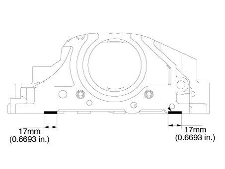
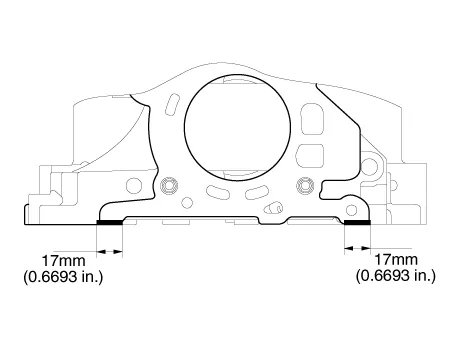
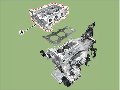
| 2. | Install the cylinder head assembly.
|
| 3. | IInstall the remaining parts in the reverse order of removal. |
Description and operation Description Continuous Variable Valve Timing (CVVT) system advances or retards the valve timing of the intake and exhaust valve in accordance with the ECM control signal which is calculated by the engine speed and load.
Other information:
Kia Picanto (JA) 2017-2026 Service & Repair Manual: Immobilizer System
Schematic diagrams Circuit Diaram Description and operation Description The immobilizer system will disable the vehicle unless the proper ignition key is used, in addition to the currently available anti-theft systems such as car alarms, the immobilizer system aims to drastically reduce the rate of auto theft.
Kia Picanto (JA) 2017-2026 Service & Repair Manual: Power Door Lock Module
Components and components location Components 1. Door lock/unlock knob cable 2. Door inside handle cable 3. Door latch assembly Repair procedures Inspection • When removing with a flat-tip screwdriver or remover, wrap protective tape around the tools to prevent damage to
Categories
- Manuals Home
- Kia Picanto Owners Manual
- Kia Picanto Service Manual
- Automatic Transaxle Fluid
- To set cruise control speed
- Charging System
- New on site
- Most important about car
