Kia Picanto (JA): Engine Control System / Camshaft Position Sensor (CMPS)
Specifications
| Camshaft Position Sensor (CMPS) |
Item
|
Specification
|
Type
| Hall effect type
|
Air Gap (mm)
| 0.5 - 1.5
|
Pin
| 3
|
Description and operation
The
Camshaft Position Sensor (CMPS) is used for detecting the camshaft
position by using a hall element, and is also called the hall sensor.
Installed on engine head cover, the CMPS uses a target wheel installed
on the camshaft to determine the position of each piston that cannot be
detected by CKPS. It is equipped with a hall-effect IC whose output
voltage changes when magnetic field is applied to the IC with current
flow. Hence, the sequential injection of each cylinder is possible with
CMPS signal.

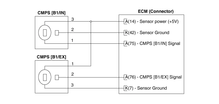
Schematic diagrams

Repair procedures
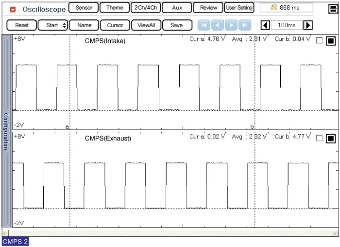
| 1. | Check the signal waveform of the CMPS and CKPS using the KDS.
Specification: Refer to “Wave Form” |
|
DO
NOT remove the camshaft position sensor while the engine is running or
immediately after turning off the engine as the part and engine oil are
hot and can cause burns. |
| 1. | Turn the ignition switch OFF and disconnect the battery negative (-) terminal. |
| 2. | Remove the air cleaner.
(Refer to Engine Mechanical System - “Air Cleaner”)
|
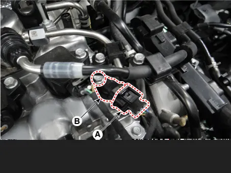
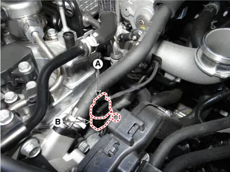
| 3. | Disconnect the camshaft position sensor connector (A). |
| 4. | Remove the sensor (B) by loosening the mounting bolt.
Camshaft position sensor mounting bolt:
9.8 - 11.8 N·m (1.0 - 1.2 kgf·m, 7.2 - 8.7 lb·ft) |
 |
| 1. | Turn the ignition switch OFF and disconnect the battery negative (-) terminal. |
| 2. | Remove the air cleaner.
(Refer to Engine Mechanical System - “Air Cleaner”)
|
| 3. | Disconnect the camshaft position sensor connector (A). |
| 4. | Remove the sensor (B) by loosening the mounting bolt.
Camshaft position sensor mounting bolt:
9.8 - 11.8 N·m (1.0 - 1.2 kgf·m, 7.2 - 8.7 lb·ft) |
 |
| •
| Install the component to the specified torques. |
| •
| Note that internal damage may occur when the component is dropped. If the component has been dropped, inspect before installing. |
| •
| Apply engine oil to the O-ring. |
| •
| Carefully insert the sensor into the installation hole without damaging it. |
| •
| Be careful not to damage the sensor housing and the connector. |
| •
| Be careful not to damage the O-ring. |
|
| 1. | Install in the reverse order of removal. |
Troubleshooting

Specifications
Specification
NON- ISG
Item
Specification
Type Magnetic field sensitive type Coil Resistance (Ω) 819 - 1001 [20°C (68°F)] Pin 2
ISG only
Item
Specification
Type Hall effect type Air Gap (mm) 0.
Specifications
Specification
Item
Specification
Resistance(MΩ) 4.87 Capacitance (pF) 850 - 1150 Type Piezo-electricity Pin 2
Description and operation
Description
Knocking
is a phenomenon characterized by undesirable vibration and noise that
can cause engine damage.
Other information:
Components and components location
Components
1. Head unit (AVN, Audio) 2. Emergency call system button 3. Emergency call system MIC 4. Roof antenna 5. Emergency call unit 6. Supplemental Restraint System Control Module (SRSCM) 7. Emergency call crash pad antenna 8.
Components and components location
Components
1. Driver side seat heater switch 2. Passenger side seat heater switch
Schematic diagrams
Circuit Diagram
Repair procedures
Removal
1. Disconnect the negative (-) battery terminal.


