Kia Picanto (JA): Engine Control System / Exhaust Gas Temperature Sensor (EGTS)
Specifications
| Specification |
|
Temperature [°C (°F)]
|
Resistance (kΩ)
|
| -40 (-40) | 0.17 |
| 0 (-32) | 0.201 |
| 100 (212) | 0.276 |
| 200 (392) | 0.35 |
| 300 (572) | 0.42 |
| 400 (752) | 0.489 |
| 500 (932) | 0.555 |
| 600 (1112) | 0.618 |
| 700 (1292) | 0.68 |
| 800 (1472) | 0.739 |
| 850 (1562) | 0.767 |
Description and operation
| Description |
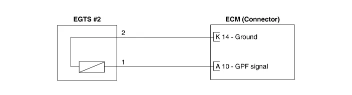
Schematic diagrams
| Circuit Diagram |

Repair procedures
| Inspection |
| 1. | Turn ignition switch OFF. |
| 2. | Disconnect the connector of exhaust gas temperature sensors #1/#2. |
| 3. | Measure resistance between sensor signal terminal and ground terminal. |
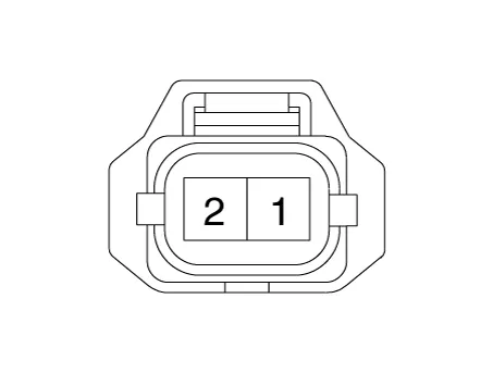
| 4. | Check that the resistance is within the specification. Exhaust Gas Temperature Sensor [EGTS #1, #2 (T3, T4)]
|
| Removal & Installation |
| 1. | Turn the ignition switch OFF and disconnect the battery negative (-) terminal. |
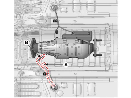
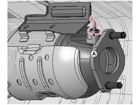
| 2. | Disconnect the EGTS connector (A). |
| 3. | Remove the EGTS (B).
|
| 4. | Install the sensor in the reverse order of removal.
|

| 1. | Turn the ignition switch OFF and disconnect the battery negative (-) terminal. |
| 2. | Disconnect the EGTS connector (A).
|
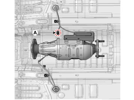
| 3. | Remove the EGTS (A).
|
| 4. | Install the sensor in the reverse order of removal.
|
Specifications Specification HO2S [Bank 1/Sensor 1] Item Specification Heater Resistance (Ω) 2.
Specifications Specification Item Specification Rated Voltage (V) 5 Operating Voltage (V) 4.
Other information:
Kia Picanto (JA) 2017-2026 Service & Repair Manual: Hazard Lamp Switch
Repair procedures Inspection 1.Check for continuity between terminals. If the continuity is not as specified, replace the hazard lamp switch. No. Description No.
Kia Picanto (JA) 2017-2026 Service & Repair Manual: Heater & A/C Control Unit(Full Automatic)
Components and components location Components Control Panel Connector pin function No. Connector A Connector B 1 Battery PAB IGN1 2 ISG Battery (+) PAB On signal 3 Illumination (+) PAB Off signal 4 Sensor REF (+5V) - 5 Mode control actua
Categories
- Manuals Home
- Kia Picanto Owners Manual
- Kia Picanto Service Manual
- Body Electrical System
- Cooling System
- Normal Condition
- New on site
- Most important about car
