Kia Picanto (JA): Engine Control System / Heated Oxygen Sensor (HO2S)
Specifications
HO2S [Bank 1/Sensor 1]
Item
|
Specification
|
Heater Resistance (Ω)
| 2.5 - 4.0 [20°C(68°F)]
|
Type
| Linear
|
Pin
| 6
|
HO2S [Bank 1/Sensor 2]
Item
|
Specification
|
Heater Resistance (Ω)
| Approximately 9.0 [20°C(68°F)]
|
Type
| Binary
|
Pin
| 4
|
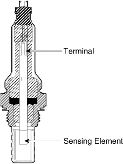
Description and operation
Installed
in both upstream and downstream of the Manifold Catalytic Converter,
the Heated Oxygen Sensor (HO2S) consists of zirconium and alumina. The
sensor output voltage varies in accordance with the air fuel ratio.
The
sensor must be heated in order to operate properly. To keep it heated,
it is equipped with a heater controlled by the ECM via a duty cycle
signal. When the exhaust gas temperature is lower than the specified
value, the heater will warm up the sensor tip.
Schematic diagrams


Repair procedures
| 1. | Turn the ignition switch OFF. |
| 2. | Disconnect the HO2S connector. |
| 3. | Measure resistance between the HO2S terminals 2 and 5 [B1/S1].
Specification : 2.4-4.0 [20°C(68°F)] |
|
| 4. | Measure resistance between the HO2S terminals 3 and 4 [B1/S2].
Specification : Approximately 9.0 [20°C(68°F)] |
|
| 5. | Check that the resistance is within the specification. |
Note that the SST 09392-1Y100 can be used for removing the heated oxygen sensor. |
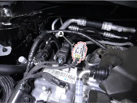
| 1. | Turn the ignition switch OFF and disconnect the battery negative (-) terminal. |
| 2. | Disconnect the connector (A). |
| 3. | Remove the heated oxygen sensor (B).
Heated oxygen sensor:
39.2 - 49.1 N·m (4.0 - 5.0 kgf·m, 28.9 - 36.2 lb·ft) |
 |
| 1. | Turn the ignition switch OFF and disconnect the battery negative (-) terminal. |
| 2. | Disconnect the connector (A).
 |
| 3. | Remove the heated oxygen sensor (A).
Heated oxygen sensor:
39.2 - 49.1 N·m (4.0 - 5.0 kgf·m, 28.9 - 36.2 lb·ft) |
 |
| •
| Install the component to the specified torques. |
| •
| Note
that internal damage may occur when the component is dropped. If the
component has been dropped, inspect before installing. |
| •
| DO
NOT use a cleaner, spray, or grease to sensing element and connector of
the sensor as oil substance may degrade the sensor performance. |
| •
| Sensor and its wiring may get damaged by contacting with the exhaust system (Exhaust Manifold, Catalytic Converter, etc.). |
|
| 1. | Install in the reverse order of removal. |
Specifications
Specification
Item
Specification
Resistance(MΩ) 4.87 Capacitance (pF) 850 - 1150 Type Piezo-electricity Pin 2
Description and operation
Description
Knocking
is a phenomenon characterized by undesirable vibration and noise that
can cause engine damage.
Specifications
Specification
Exhaust Gas Temperature Sensor (EGTS) #1, 2
▷ Type : Thermistor type
Temperature [°C (°F)]
Resistance (kΩ)
-40 (-40) 0.
Other information:
Components and components location
Component Location
1. Driver power window switch 2. Assist power window switch 3. Rear power window switch 4. Front window motor 5. Rear window motor
Description and operation
Safety Function of Power Window
When driver door power window auto-up switch is operated, safety function is acti
Repair procedures
Replacement
1.Disconnect the negative (-) battery terminal.
2.Remove the heater unit.
(Refer to Heater - "Heater Unit")
3.Remove the Evaporator temperature sensor.
(Refer to Air Conditioning System - "Evaporator Temperature Sensor")
4.

