Kia Picanto (JA): Engine Control System / ETC (Electronic Throttle Control) System
Specifications
Sensor
Item
|
Opening Percentage (%)
|
Output Voltage (V) [Vref = 5V]
|
TPS1
| C.T
| 8.5 - 11.5
| 0.43 - 0.58
|
W.O.T
| 88 - 96
| 4.40 - 4.80
|
TPS2
| C.T
| 88.5 - 91.5
| 4.43 - 4.58
|
W.O.T
| 2 - 10
| 0.10 - 0.50
|
Fail Safe
| Throttle valve stuck at 5°
|
Supply Voltage (V)
| 4.8 - 5.2
|
Type
| Hall IC Non-contact sensor [Integrated into ETC Module]
|

Motor
Item
|
Specification
|
Coil Resistance (Ω)
| 0.3 - 100 [20°C(68°F)]
|
Maximum Allowable Current (A)
| < 10.0
|
Type
| DC Motor [Integrated into ETC Module]
|
Description and operation
The
Electronic Throttle Control (ETC) System consists of a throttle body
with an integrated control motor and throttle position sensor (TPS).
Instead of the traditional throttle cable, an Accelerator Position
Sensor (APS) is used to receive driver input. The ECM uses the APS
signal to calculate the target throttle angle; the position of the
throttle is then adjusted via ECM control of the ETC motor. The TPS
signal is used to provide feedback regarding throttle position to the
ECM. Using ETC, precise control over throttle position is possible; the
need for external cruise control modules/cables is eliminated.
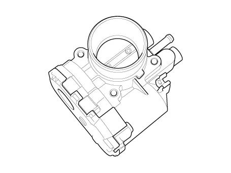

1. Dry bearing
2. DC motor
3. Non-contact hall sensor
4. Gear
| 5. Magnet
6. Hall IC
7. Yoke
8. Stator
|

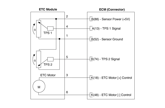
Schematic diagrams

Repair procedures
Throttle Position Sensor (TPS)
| 1. | Connect the KDS on the Data Link Connector (DLC). |
| 2. | Start the engine and measure the output voltage of TPS 1 and 2 at C.T. and W.O.T.
Item
|
Opening Percentage (%)
|
Output Voltage (V) [Vref = 5V]
| TPS1
| C.T
| 8.5 - 11.5
| 0.43 - 0.58
| W.O.T
| 88 - 96
| 4.40 - 4.80
| TPS2
| C.T
| 88.5 - 91.5
| 4.43 - 4.58
| W.O.T
| 2 - 10
| 0.10 - 0.50
|
|
ETC Motor
| 1. | Turn the ignition switch OFF. |
| 2. | Disconnect the ETC module connector. |
| 3. | Measure resistance between the ETC module terminals 1 and 2. |
| 4. | Check that the resistance is within the specification.
Specification : 0.3 - 100 Ω [20°C(68°F)] |
|
| 1. | Turn the ignition switch OFF and disconnect the battery negative (-) terminal. |
| 2. | Remove the air cleaner.
(Refer to Engine Mechanical System - “Air Cleaner”)
|
| 3. | Disconnect the ETC module connector (A). |
| 4. | Remove the installation bolts (B) and then remove the ETC module from the engine.
Electronic Throttle Control module mounting bolt :
9.8 - 11.8 N·m (1.0 - 1.2 kgf·m, 7.2 - 8.7 lb·ft) |
 |
| 1. | Remove the ETC Module.
(Refer to Engine Control System - "ETC System")
|
| 2. | Keep the ETC module plate (A) open.
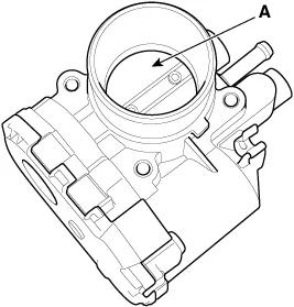 |
| 3. | Clean the pollutant in the throttle body using a soft cloth moistened with clearning fluid.
 | •
| Do not directly spray cleaning fluid to ETC module. Instead, use a lint free cloth moistened with cleaning fluid. |
| •
| Be
careful not to remove the coating fluid around the shaft. If coating
fluid is removed, idling control failure may occur due to inflow of
foreign substances or excessive air leakage. |
|
|
| 4. | After cleaning, reinstall the ETC module and then perform the ETC module learning procedure.
(Refer to Engine Control System - "ETC System" - Adjustment)
|
| •
| Install the component to the specified torques. |
| •
| Note that internal damage may occur when the component is dropped. If the component has been dropped, inspect before installing. |
| •
| When cleaning the throttle body, clean the valve and carbon at the bore using a cloth moistened with cleaner. |
| •
| Do not spray the engine cleaner on the throttle body. |
| •
| Be careful as fingers or cloth may get caught in the valve. |
| •
| When installing the throttle body, keep foreign materials away from the throttle body. |
| •
| Fill with engine coolant.
(Refer to Engine Mechanical System - "Coolant")
|
|
| 1. | Install in the reverse order of removal. |
| ETC module learning procedure |
Be sure to perform the ETC module learning procedure when replacing or reinstalling the ETC module.
| 1. | Wait for 1 minute with the ignition switch ON. |
| 2. | Start the engine and keep it idle for 15 minutes. |
| 3. | Waif for 1 minute with the ignition switch OFF. |
| 4. | Restart the engine, and check that the idle speed is stable. If
the ETC module learning procedure is not performed after replacing or
reinstalling the ETC module, MIL illumination with DTCs may occur. |
|
Troubleshooting
Item
|
Fail-Safe
|
ETC Motor
| Throttle valve stuck at 5°
|
TPS
| TPS 1 fault
| ECM looks at TPS2
|
TPS 2 fault
| ECM looks at TPS1
|
TPS 1,2 fault
| Throttle valve stuck at 5°
|
APS
| APS 1 fault
| ECM looks at APS 2
|
APS 2 fault
| ECM looks at APS 1
|
APS 1,2 fault
| Engine idle state
|
When
throttle value is stuck at 5°, engine speed will be limited to below
1,500 rpm and vehicle speed at maximum 40 - 50 km/h (25-31 mph). |
Schematic diagrams
ECM Terminal and Input/Output signal [M/T]
1. Harness Connector
2. Terminal Function [M/T]
[Connector A]
Pin No
Description
1 Ignition coil (Cylinder #3) control output 2 Ignition coil (Cylinder #2) control output 3 - 4 Electric Waste Gate Actuator (EWGA) Motor [+] control output 5 Injector (Cylinder #3) [Low] control output 6 - 7 Engine Coolant Temperature Sensor (ECTS) signal input 8 - 9 Boost Pressure Sensor (BPS) signal input 10 - 11 - 12 Electric Waste Gate Actuator (EWGA) Feed beck signal input 13 Throttle Position Sensor (TPS) 1 signal input 14 Accelerator Position Sensor (APS) 1 signal input 15 Brake Booster Vacuum Pressure Sensor (BBVPS) signal input 16 - 17 Ignition coil (Cylinder #1) control output 18 ETC motor [+] control output 19 Electric Waste Gate Actuator (EWGA) DC Motor [-] control output 20 Injector (Cylinder #2) [Low] control output 21 Wiper switch signal input 22 Neutral Switch signal input 23 - 24 Camshaft Position Sensor (CMPS) [Bank 1/Exhaust] signal input 25 A/C dual pressure switch signal input 26 Vehicle speed signal input 27 Start signal input 28 Brake Test switch signal input 29 Brake Light switch signal input 30 Clutch switch signal input 31 Injector (Cylinder #2) [High] control output 32 Injector (Cylinder #3) [High] control output 33 - 34 Injector (Cylinder #1) [Low] control output 35 Fuel Pressure Control Valve (FPCV) [High] control output 36 Camshaft position sensor (CMPS) [Bank 1/Intake] ground 37 Camshaft position sensor (CMPS) [Bank 1/Exhaust] ground 38 - 39 - 40 - 41 Heated Oxygen Sensor (HO2S) [Bank 1/Sensor 2] signal input 42 - 43 Battery Sensor Temperature signal input 44 ISG OFF switch signal input 45 Electric load signal input [Defrost] 46 - 47 Injector (Cylinder #1) [High] control output 48 ETC motor [-] control output 49 - 50 Fuel Pressure Control Valve (FPCV) [Low] control output 51 Wheel speed sensor [A] signal input 52 Wheel speed sensor [B] signal input 53 Crankshaft Position Sensor (CKPS) ground 54 Crankshaft Position Sensor (CKPS) signal input 55 - 56 Camshaft Position Sensor (CMPS) [Bank 1/Intake] signal input 57 Heated Oxygen Sensor (HO2S) [Bank 1/Sensor 2] ground 58 - 59 Battery Sensor Current Direct signal input 60 -
[Connector B]
Pin No
Description
1 ECM ground 2 ECM ground 3 ECM ground 4 Battery power (B+) 5 Battery power (B+) 6 Battery power (B+) 7 Battery power (B+) 8 Accelerator Position Sensor (APS) #1 ground 9 Manifold Air Temperature Sensor (MAPS) ground 10 Boost Pressure Sensor (BPS) ground 11 - 12 Electric Waste Gate Actuator (EWGA) ground 13 - 14 - 15 - 16 Engine Coolant Temperature Sensor (ECTS) ground 17 - 18 - 19 - 20 A/C compressor relay control output 21 - 22 CVVT Oil Control Valve (OCV) [Bank 1/Intake] control output 23 - 24 Cooling fan PWM control output 25 - 26 - 27 Fuel pump relay control output (With Immobilizer/Smart key) 28 - 29 Ignition switch signal input 30 Accelerator Position Sensor (APS) #2 ground 31 - 32 - 33 Battery sensor ground 34 - 35 - 36 Rail Pressure Sensor (RPS) ground 37 - 38 - 39 - 40 - 41 Start relay [Low] control output 42 - 43 Accelerator Position Sensor (APS) #2 power (+5V) 44 Camshaft Position Sensor (CMPS) power (+5V) 45 - 46 ISG OFF lamp signal output 47 - 48 - 49 - 50 CVVT Oil Control Valve (OCV) [Bank 1/Exhaust] control output 51 Main relay control output 52 Throttle Position Sensor (TPS) ground 53 Blower Switch MAX.
Specifications
Specification
Pressure
[kPa (kgf/cm², psi)]
Output Voltage (V) [Vref=5V]
32.
Other information:
Components and components location
Component Location
1. Back view camera 2. AVN head unit 3. steering angle sensor
Description and operation
Description
1. To
display back of the vehicle to assist the driver, it receives vehicle
rearside image signal from the rearview camera and displays it on AVN
head unit monitor
Repair procedures
Replacement
1.Disconnect the negative (-) battery terminal.
2.Remove the heater unit.
(Refer to Heater - "Heater Unit")
3.Remove the Evaporator temperature sensor.
(Refer to Air Conditioning System - "Evaporator Temperature Sensor")
4.

