Kia Picanto (JA): Engine Control System / Manifold Absolute Pressure Sensor (MAPS)
Specifications
Pressure
[kPa (kgf/cm², psi)]
|
Output Voltage (V) [Vref=5V]
|
32.5 (0.33, 4.71)
| 0.5
|
284 (2.90, 41.19)
| 4.5
|
Description and operation
Installed
on the surge tank, Manifold Absolute Pressure Sensor (MAPS) is a
speed-density type sensor that senses absolute pressure of the surge
tank and transfers the analog signal proportional to the pressure to the
ECM. By using this signal, the ECM calculates the intake air amount and
engine speed.
The
MAPS consists of a piezo-electric element and a hybrid IC amplifying
the element output signal. This element, a silicon diaphragm type,
features pressure sensitive variable resistor effect of semi-conductor.
Due to 100% vacuum status and manifold pressure applied to both sides of
the sensor, this sensor can output analog signal by using the silicon
variation proportional to pressure change.

Schematic diagrams


Repair procedures
| 1. | Connect the KDS on the Data Link Connector (DLC). |
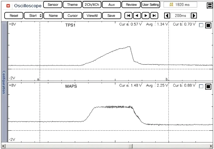
| 2. | Measure the output voltage of the MAPS at idle and IG ON.
Pressure
[kPa (kgf/cm², psi)]
|
Output Voltage (V) [Vref=5V]
| 32.5 (0.33, 4.71)
| 0.5
| 284 (2.90, 41.19)
| 4.5
|
|
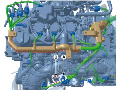
| 1. | Turn the ignition switch OFF and disconnect the battery negative (-) terminal. |
| 2. | Disconnect the manifold absolute pressure sensor connector (A). |
| 3. | Remove the sensor (B) from the Intake manifold by loosening the mounting screws.
Manifold absolute pressure sensor mounting screw :
6.4 - 8.3 N·m (0.65 - 0.85 kgf·m, 4.7 - 6.1 lb·ft) |
 |
| •
| Tighten the component to the specified torques. |
| •
| Note
that internal damage may occur when the component is dropped. If the
component has been dropped, if it is damaged inspect before installing. |
| •
| Carefully insert the sensor into the installation hole without damaging it. |
|
| 1. | Install in the reverse order of removal. |
Troubleshooting
Specifications
Specification
Sensor
Item
Opening Percentage (%)
Output Voltage (V) [Vref = 5V]
TPS1 C.
Specifications
Specification
▷ Type: Thermistor type
Temperature
Resistance (kΩ)
°C
°F
-40 -40 40.
Other information:
Specifications
Specifications
[BCM Type]
Items
Specifications
Rated voltage DC 12 V Operating voltage DC 9 - 16 V Operating temperature -31 - 167°F (-35 - 75°C) Dark current SMK : 3mA / Keyless : 3.
Repair procedures
Inspection
1.Disconnect the key warning switch connector (A) and ignition switch connector (B) from the steering column.
2.Check for continuity between the terminals.
3.If continuity is not specified, replace the switch.

