Kia Picanto (JA): Engine Control System / Knock Sensor (KS)
Kia Picanto (JA) 2017-2026 Service & Repair Manual / Engine Control / Fuel System / Engine Control System / Knock Sensor (KS)
Specifications
| Specification |
|
Item
|
Specification
|
| Resistance(MΩ) | 4.87 |
| Capacitance (pF) | 850 - 1150 |
| Type | Piezo-electricity |
| Pin | 2 |
Description and operation
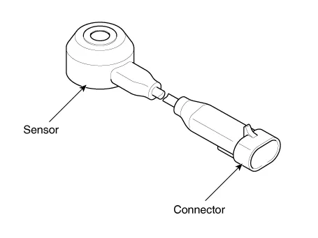
| Description |
Knocking
is a phenomenon characterized by undesirable vibration and noise that
can cause engine damage. Installed on the cylinder block, Knock Sensor
(KS) senses engine knocking.
When
knocking occurs, the vibration from the cylinder block is applied as
pressure to the piezoelectric element. When knocking occurs, the sensor
produces voltage signal. The ECM retards the ignition timing when
knocking occurs. If the knocking disappears after retarding the ignition
timing, the ECM will advance the ignition timing. This sequential
control can improve engine power, torque and fuel economy.
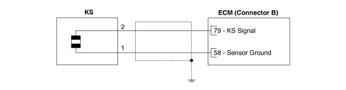
Schematic diagrams
| Circuit Diagram |
| [A/T] |

| [M/T] |
Repair procedures
| Removal |
| 1. | Turn the ignition switch OFF and disconnect the battery negative (-) terminal. |
| 2. | Remove the intake manifold.
(Refer to Engine Mechanical System - "Intake Manifold")
|
| 3. | Remove the delivery pipe.
(Refer to Fuel Delivery System - "Delivery Pipe")
|
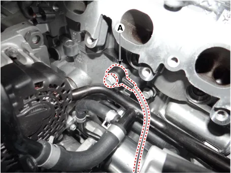
| 4. | Remove the knock sensor (A) after loosening the mounting bolt.
|
| Installation |
|

| 1. | Install in the reverse order of removal. |
Specifications Camshaft Position Sensor (CMPS) Item Specification Type Hall effect type Air Gap (mm) 0.
Specifications Specification HO2S [Bank 1/Sensor 1] Item Specification Heater Resistance (Ω) 2.
Other information:
Kia Picanto (JA) 2017-2026 Service & Repair Manual: Emergency Call (eCall) Button
Components and components location Component Repair procedures Removal 1. Disconnect the negative (-) battery terminal. 2. Using a screwdriver or remover, separate the map lamp lens (A) from the map lamp. 3. Remove the map lamp (A) after loosening the screws.
Kia Picanto (JA) 2017-2026 Service & Repair Manual: Headlamp Leveling System
C
Categories
- Manuals Home
- Kia Picanto Owners Manual
- Kia Picanto Service Manual
- Front Disc Brake
- Engine Mechanical System
- To set cruise control speed
- New on site
- Most important about car

Copyright © 2026 www.kpicanto.com - 0.021