Kia Picanto (JA): Heating,Ventilation, Air Conditioning
Specifications
| Specification |
|
Item
|
Specification
| ||
| Compressor | Type | 5VSe09(Variable Dispacement Swashplate) | 5VS09 |
| Oil type & Capacity | FD46XG(PAG) 100±10g | ||
| Pulley type | POLY V RIBBED BEIT 6PK | ||
| Displacement | 90cc/rev | ||
| Condenser | Heat rejection | 9,890 -3% kcal/hr | |
| A/C Pressure transducer | The method to measure the pressure | DUEL Switch | Voltage= 0.00878835 * Presure (psig) + 0.5 |
| Expansion valve | Type | Block type | |
| Refrigerant | Type | R-134a, R-1234yf | |
| Capacity [oz.(g)] | 370 ± 25g | ||
|
Item
|
Specification
| |
| Fresh and recirculation | Operating method | Actuator |
| Blower | Type | Sirocco |
| Speed step | 1~4speed (Manual), Auto + 8 speed (FATC) | |
| Speed control | Resistor(manual), Mosfet (FATC) | |
| Air filter | Type | Particle filter |
|
Item
|
Specification
| |
| Heater | Type | Pin & Tube type |
| Heating capacity | 4,400 - 5% kcal/hr | |
| Mode operating method | Manual (Cable), FATC (Actuator) | |
| Temperature operating method | Manual (Cable), FATC (Actuator) | |
| Evaporator | Temperature control type | Evaporator temperature sensor |
| A/C ON/OFF [°C(°F)] | ON: 4.4 ± 0.4 (39.9 ± 32.7), OFF: 2.9 ± 0.4 (37.2 ± 32.7) | |
Special service tools
| Special Service Tools |
|
Tool (Number and name)
|
Illustration
|
Use
|
| 09977-29000 Disc & hub assembly bolt remover |
| Removal and installation of disc & hub assembly |

Troubleshooting
| Troubleshooting |
| Problem Symptoms Table |
|
Symptom
|
Suspect Area
|
| No blower operation | 1. Blower fuse |
| 2. Blower motor | |
| 3. Power mosfet | |
| 4. Blower speed control switch | |
| 5. Wire harness | |
| No air temperature control | 1. Engine coolant capacity |
| 2. Heater control assembly | |
| No compressor operation | 1. Refrigerant capacity |
| 2. A/C Fuse | |
| 3. Magnetic clutch | |
| 4. Compressor | |
| 5. A/C pressure transducer | |
| 6. A/C switch | |
| 7. Evaporator temperature sensor | |
| 8. Wire harness | |
| No cool comes out | 1. Refrigerant capacity |
| 2. Refrigerant pressure | |
| 3. Drive belt. | |
| 4. Magnetic clutch | |
| 5. Compressor | |
| 6. A/C pressure transducer | |
| 7. Evaporator temperature sensor | |
| 8. A/C switch | |
| 9. Heater control assembly | |
| 10. Wire harness | |
| Insufficient cooling | 1. Refrigerant capacity |
| 2. Drive belt | |
| 3. Magnetic clutch | |
| 4. Compressor | |
| 5. Condenser | |
| 6. Expansion valve | |
| 7. Evaporator | |
| 8. Refrigerant lines | |
| 9. A/C pressure transducer | |
| 10. Heater control assembly | |
| No engine idle-up when A/C switch ON | 1. Engine ECM |
| 2. Wire harness | |
| No air inlet control | 1. Heater control assembly |
| No mode control | 1. Heater control assembly |
| No cooling fan operation | 1. Cooling fan fuse |
| 2. Fan motor | |
| 3. Engine ECM | |
| 4. Wire harness |
Air Conditioning System
General safety information and caution
| Instructions |
| 1. | R-134a
liquid refrigerant is highly volatile. A drop on the skin of your hand
could result in localized frostbite. When handling the refrigerant, be
sure to wear gloves. |
| 2. | It
is standard practice to wear goggles or glasses to protect your eyes,
and gloves to protect your hands. If the refrigerant splashes into your
eyes, wash them with clean water immediately. |
| 3. | The R-134a container is highly pressurized. Never leave it in a hot place, and check storage temperature is below 52°C (126°F). |
| 4. | An
electronic leak detector should be used to check the system for
refrigerant leakage. Bear in mind that the R-134a, upon coming into
contact with flame, produces phosgene, a highly toxic gas. |
| 5. | Use only recommended lubricant for R-134a systems. If lubricants other than the recommended one used, system failure may occur. |
| 6. | PAG lubricant absorbs moisture from the atmosphere at a rapid rate, therefore the following precautions must be observed:
|
| 7. | If an accidental discharge in the system occurs, ventilate the work area before resum of service.
|
| 1. | Never open or loosen a connection before discharging the system. |
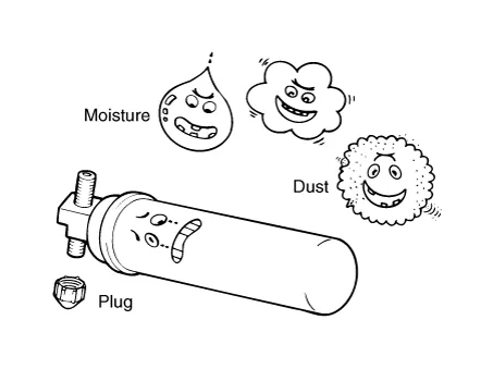
| 2. | Seal the open fittings of components with a cap or plug immediately to prevent intrusion of moisture or dust. |
| 3. | Do not remove the sealing caps from a Replacement component until it is ready to be installed. |
| 4. | Before
connecting an open fitting, always install a new sealing ring. Coat the
fitting and seal with refrigerant oil before making the connection.
|
|

| 1. | When
it is necessary to open the refrigeration system, have everything you
will need to service the system ready so the system will not be left
open any longer than necessary. |
| 2. | Cap or plug all lines and fittings as soon as they are opened to prevent the entrance of dirt and moisture. |
| 3. | All lines and components in parts stock should be capped or sealed until they are ready to be used. |
| 4. | Never attempt to rebind formed lines to fit. Use the correct line for the installation you are servicing. |
| 5. | All tools, including the refrigerant dispensing manifold, the gauge set manifold and test hoses, should be kept clean and dry. |
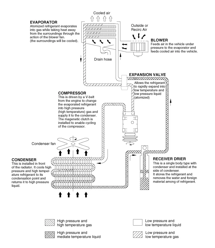
Description and operation
| Refrigeration Cycle |
Repair procedures
| Refrigerant System Service Basics |
|

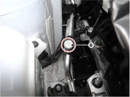
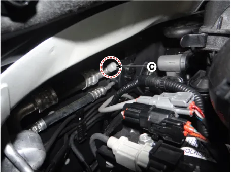
| 1. | Connect an R-134a refrigerant Recovery/Recycling/Charging
System (A) to the high-pressure service port (B) and the low-pressure
service port (C) as shown, following the equipment manufacturer's
instructions.
|

| 2. | Measure
the amount of refrigerant oil removed from the A/C system after the
recovery process is completed. Be sure to install the same amount of new
refrigerant oil back into the A/C system before charging. |
|
| 1. | When
an A/C System has been opened to the atmosphere, such as during
installation or repair, it must be evacuated using an R-134a refrigerant
Recovery/Recycling/Charging System. (If the system has been open for
several days, the receiver/dryer should be replaced, and the system
should be evacuated for several hours.) |
| 2. | Connect an R-134a refrigerant Recovery/Recycling/Charging
System (A) to the high-pressure service port (B) and the low-pressure
service port (C) as shown, following the equipment manufacturer's
instructions.
|
| 3. | If
the low-pressure does not reach more than 93.3 kPa (700 mmHg, 27.6
in.Hg) in 10 minutes, there is probably a leak in the system. Partially
charge the system, and check for leaks (see Leak Test.). |
| 4. | Remove the low pressure valve from the low-pressure service port. |
|
| 1. | Connect an R-134a refrigerant Recovery/Recycling/Charging
System (A) to the high-pressure service port (B) as shown, following
the equipment manufacturer's instructions.
|
| 2. | Add
the same amount of new refrigerant oil to system that was removed
during recovery. Use only specified refrigerant oil. Charge the system
with 13.05 ± 0.88oz. (370 ± 25g) of R-134a refrigerant. Do not
overcharge the system the compressor will be damaged. |
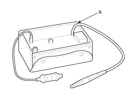
In order to use the leak detector properly, read the manual supplied by the manufacturer. |
| 1. | Check
the torque on the connection fittings and, if too loose, tighten to the
proper torque. Check for gas leakage with a leak detector (A). |
| 2. | If
leakage continues even after the fitting has been tightened, discharge
the refrigerant from the system, disconnect the fittings, and check
their seating faces for damage. Always replace, even if the damage is
slight. |
| 3. | Check the compressor oil and add oil if required. |
| 4. | Charge the system and recheck for gas leaks. If no leaks are found, evacuate and charge the system again.
|
Components and components location
| Component Location Index |
| Engine Room |
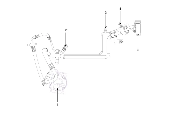
| 1. Compressor 2. A/C pressure transducer 3. Service port (High) | 4. Service port (Low) 5. Expention Valve |
| Interior |

| 1. Photo Sensor 2. A/C & Heater Controller (Manual) 3. A/C & Heater Controller (FATC) | 4. Heater & Blower Unit 5. Evaporator Sensor |
Compressor Oil
Repair procedures
| Oil Specification |
| 1. | The
HFC-134a system requires synthetic (PAG) compressor oil whereas the
R-12 system requires mineral compressor oil. The two oils must never be
mixed. |
| 2. | Compressor (PAG) oil varies according to compressor model. Be sure to use oil specified for the model of compressor. |
| 1. | The oil should be free from moisture, dust, metal powder, etc. |
| 2. | Do not mix with other oil. |
| 3. | The
water content in the oil increases when exposed to the air. After use,
seal oil from air immediately. (HFC-134a Compressor Oil absorbs moisture
very easily.) |
| 4. | The compressor oil must be stored in steel containers, not in plastic containers. |
Oil total volume in system
PAG OIL : 100 ± 10 g |
| 1. | Open all the doors and the engine hood. |
| 2. | Start the engine and air conditioning switch to "ON" and set the blower motor control knob at its highest position. |
| 3. | Run the compressor for more than 20 minutes between 800 and 1,000 rpm in order to operate the system. |
| 4. | Stop the engine. |
|
Component parts to be installed
|
Amount of Oil
|
| Evaporator | 50 g (1.70 fl.oz) |
| Condenser | 30 g (1.02 fl.oz) |
| Receiver/dryer | 30 g (1.02 fl.oz) |
| Refrigerant line (One piece) | 10 g (0.34 fl.oz) |
Even if no oil is drained from the removed compressor, don’t drain more than 50cc from new compressor. |
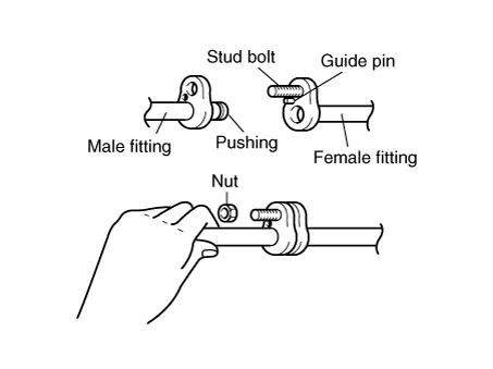
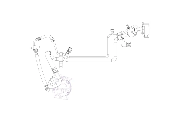
Refrigerant line
Components and components location
| Component Location |
Repair procedures
| Replacement |
| 1. | Discharge refrigerant from refrigeration system. |
| 2. | Replace faulty tube or hose.
|
| 3. | Tighten joint of bolt or nut to specified torque.
|
| 4. | Evacuate air in refrigeration system and charge system with refrigerant.
|
| 5. | Inspect for leakage of refrigerant. Using a gas leak detector, check for leakage of refrigerant. |
| 6. | Inspect A/C operation. |
Compressor
Components and components location
| Components [5VSe09] |
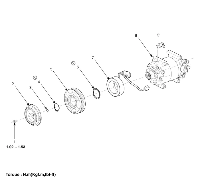
| 1. Bolt 2. Disc & Hub Assembly 3. Gap Washer (Shim) 4. Retainer Ring | 5. Pulley 6. Retainer Ring 7. Field Coil 8. Compressor Assembly |
| Components [5CS09] |
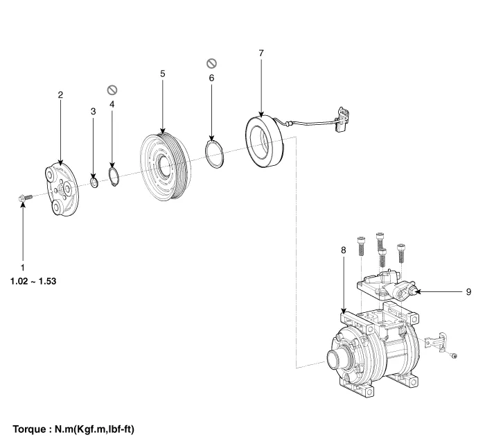
| 1. Bolt 2. Disc & Hub Assembly 3. Gap Washer (Shim) 4. Retainer Ring 5. Pulley | 6. Retainer Ring 7. Field Coil 8. Compressor Assembly 9. Manifold |
Repair procedures
| Removal |
| 1. | If
the compressor is marginally operable, run the engine at idle speed,
and let the air conditioning work for a few minutes, then shut the
engine off. |
| 2. | Disconnect the negative cable from the battery. |
| 3. | Recover the refrigerant with a recovery/charging station. |
| 4. | Disconnect the drive belt.
G 1.0 MPI-KAPPA(Refer to Engine Mechanical System - "Drive Belt")
G 1.2 MPI-GAMMA(Refer to Engine Mechanical System - "Drive Belt")
F 1.0 KAPPA FFV(Refer to Engine Mechanical System - "Drive Belt")
G 1.0 T-GDI KAPPA(Refer to Engine Mechanical System - "Drive Belt")
|
| 5. | Remove the intercooler. [G 1.0 T-GDI KAPPA]
G 1.0 T-GDI KAPPA(Refer to Engine Mechanical System - "Intercooler")
|
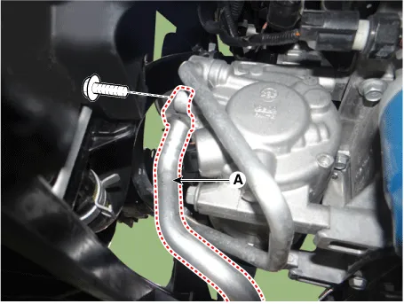
| 6. | Remove the bolts, than disconnect the discharge line (A) and suction line (B) from the compressor.
|
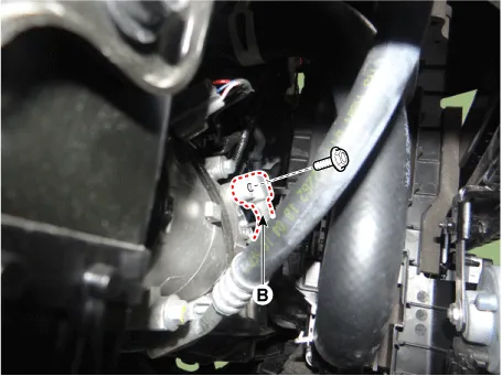
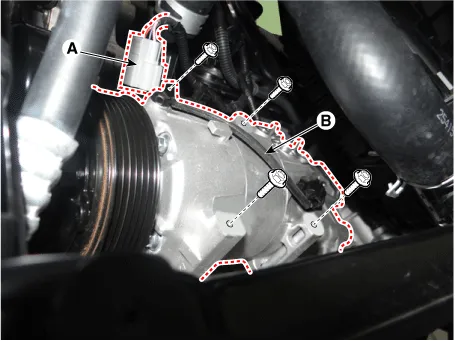
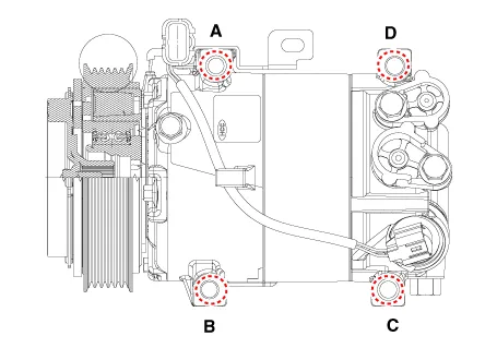
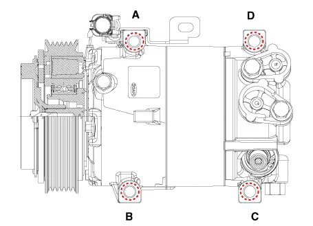
| 7. | Disconnect the compressor clutch connector (A), and then remove mounting bolts and the compressor (B).
[5VSe09]
[5VS09]
|
| Installation |
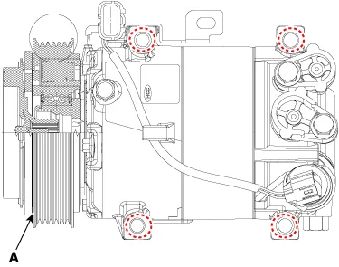
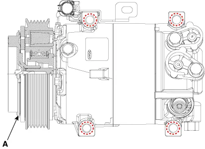
| 1. | Make sure of the length of compressor mounting bolts, and then tighten it A→B→C→D order.
[5VSe09]
[5CS09]
|
| 2. | Install in the reverse order of removal, and note these items.
|
| Inspection |
| 1. | Check
the plated parts of the limiter & hub assembly (A) for color
changes, peeling or other damage. If there is damage, replace the
assembly. |
| 2. | Check
the pulley (B) bearing play and drag by rotating the pulley by hand.
Replace the pulley with a new one if it is noisy or has excessive
play/drag.
|

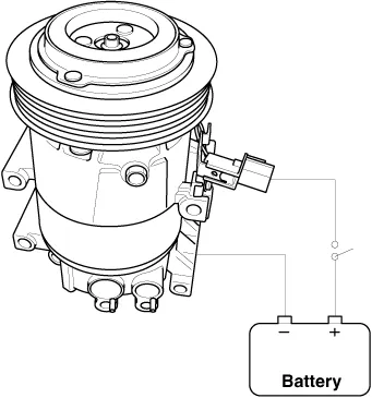
| 3. | Check operation of the magnetic clutch. Connect
the compressor side terminals to the battery (+) terminal and the
ground battery (-) terminal to the compressor body.Check the magnetic
clutch operating noise to determine the condition.
|
| Disassembly |
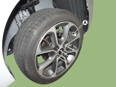
| 1. | Remove the front left tire (A) from hub.
|
| 2. | Remove the engine room under cover.
G 1.0 MPI-KAPPA (Refer to Engine Mechanical System - "Engine Room Under Cover")
G 1.2 MPI-GAMMA (Refer to Engine Mechanical System - "Engine Room Under Cover")
F 1.0 KAPPA FFV (Refer to Engine Mechanical System - "Engine Room Under Cover")
G 1.0 T-GDI KAPPA (Refer to Engine Mechanical System - "Engine Room Under Cover")
|
| 3. | Remove the front wheel guard.
(Refer to Body - "Front Wheel Guard")
|
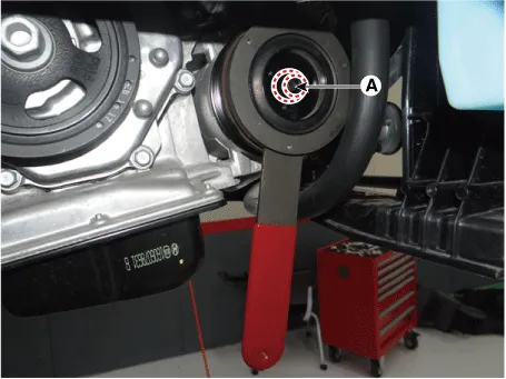
| 4. | Remove the center bolt (A) while holding the disc & hub assembly with SST( 09977-29000).
|
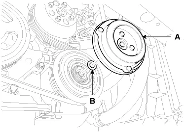
| 5. | Remove the disc & hub assembly (A) and shim (gap washer) , taking care not to lose the shims (B).
|
| 6. | Loosen the drive belt.
G 1.0 MPI-KAPPA(Refer to Engine Mechanical System - "Drive Belt")
G 1.2 MPI-GAMMA(Refer to Engine Mechanical System - "Drive Belt")
F 1.0 KAPPA FFV(Refer to Engine Mechanical System - "Drive Belt")
G 1.0 T-GDI KAPPA(Refer to Engine Mechanical System - "Drive Belt")
|
| 7. | Disconnect the retainer ring (A) and then remove the pulley (B).
|

| 8. | Remove the retainer ring (A) and then remove the field coil (B). Be careful not to damage the coil and compressor.
|

| 9. | Reassemble the compressor clutch in the reverse order of disassembly, and note these items :
|
Condenser
Components and components location
| Component Location |
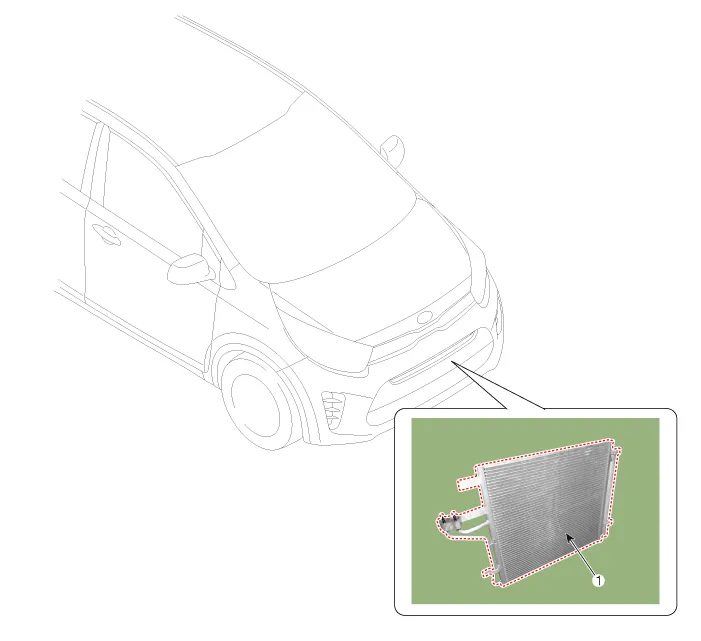
| 1. Condenser |
Repair procedures
| Removal |
| 1. | Recover the refrigerant with a recovery/recycling/charging station. |
| 2. | Disconnect the negative (-) battery terminal. |
| 3. | Remove the front bumper.
(Refer to Body - "Front Bumper Assembly")
|
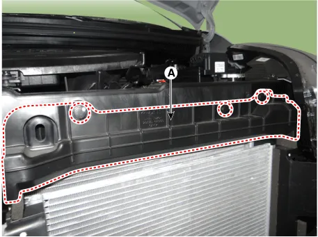
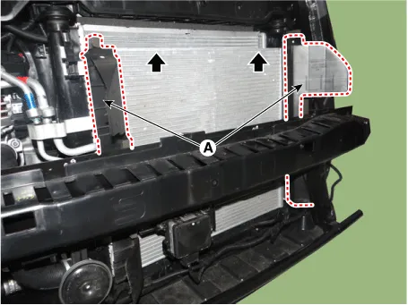
| 4. | Remove the air guard (A) after loosening the fastener.
|
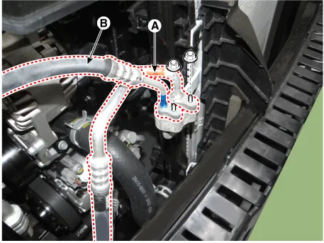
| 5. | Remove the discharge line (A) and liquid line (B) from the condenser after loosening the nuts.
|
| 6. | Remove the side air guard (A).
|
| 7. | Remove the condenser assembly (A).
|

| 8. | Install in the reverse order of removal. |
Receiver-Drier
Repair procedures
| Replacement |
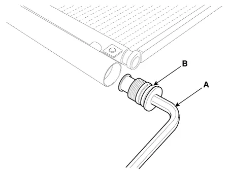
| 1. | Remove the condenser, and then remove the bottom cap (B) with L wrench (A) from the condenser.
|
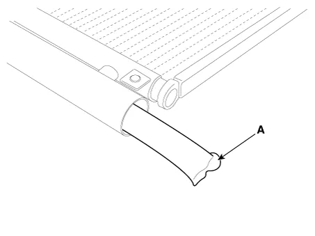
| 2. | Remove the desiccant (A) from condenser using a long nose plier. Check for crumbled desiccant and clogged bottom cap filter.
|
| 3. | Apply air conditioning compressor oil along the O-rings and threads of the new bottom cap. |
| 4. |
Insert the new desiccant into the receiver drier tank. The desiccant
must be sealed in vacuum before it is exposed to air for use. |
| 5. | Install the new bottom cap to the condenser.
|
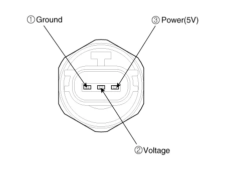
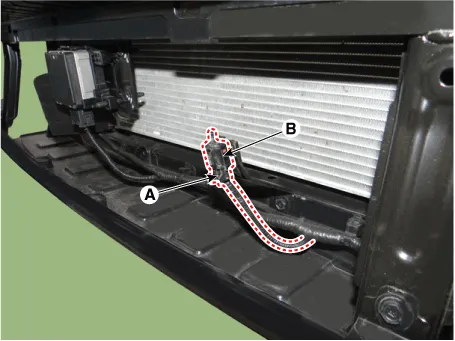
A/C Pressure Transducer
Components and components location
| Component Location |
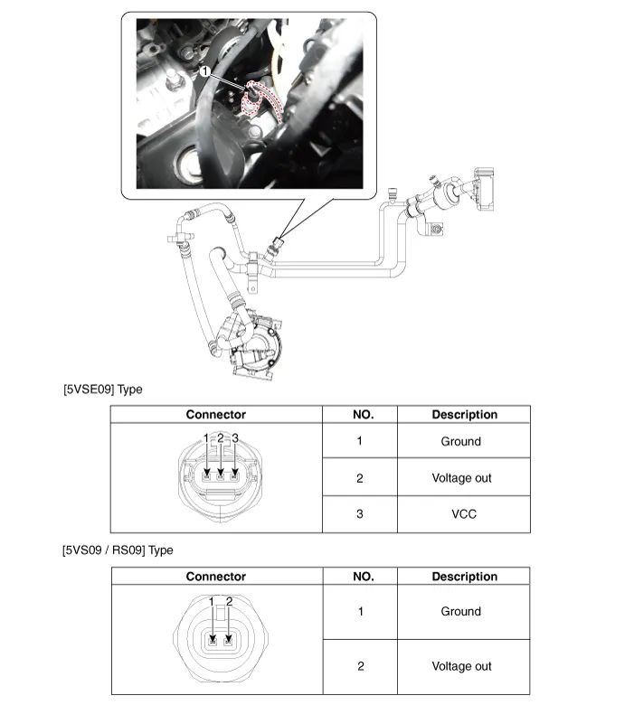
| 1. A/C Pressure Transducer |
Description and operation
| Description |
Repair procedures
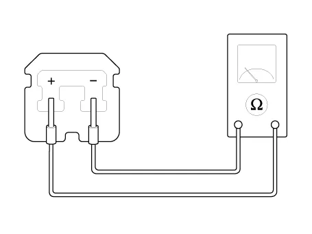
| Inspection |
| 1. | Measure the pressure of high pressure line by measuring voltage output between NO.1 and NO.2 terminals.
|
| 2. | Inspect the voltage value whether it is sufficient to be regular value or not.
|
| 3. | If the measured voltage value is not specification, replace the A/C pressure transducer. |
| Replacement |
| 1. | Disconnect the negative (-) battery terminal. |
| 2. | Recover the refrigerant with a recovery/charging station. |
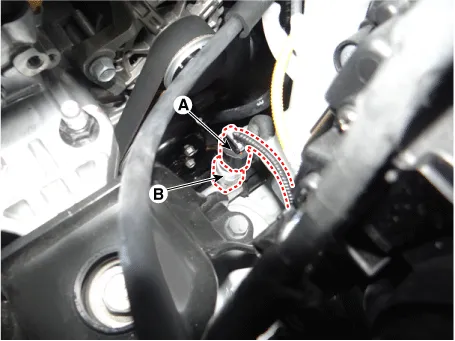
| 3. | Disconnect the A/C pressure transducer connector (A). |
| 4. | Remove the A/C pressure transducer (B).
|
| 5. | Install in the reverse order of removal. |
Evaporator Temperature Sensor
Description and operation
| Description |
Repair procedures
| Inspection |
| 1. | Ignition "OFF". |
| 2. | Disconnect evaporator temperature sensor. |
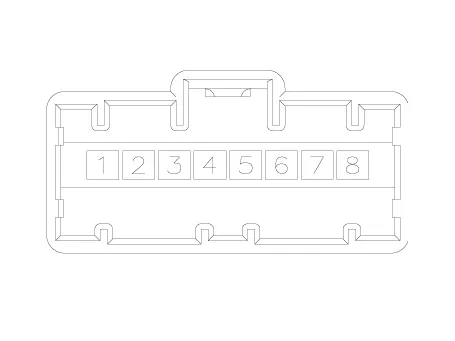
| 3. | Using the multi-tester, Measure resistance between terminal "1" and "2" of evaporator temperature sensor.
Specification
|
| Replacement |
| 1. | Disconnect the negative (-) battery terminal. |
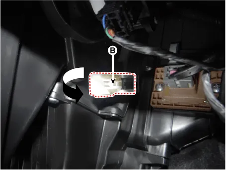
| 2. | Remove the evaporator temperature sensor (B), by pulling it after rorating 90° in a counter clock wise direction.
|

| 3. | Install in the reverse order of removal. |
Photo Sensor
Description and operation
| Description |
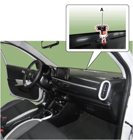
| 1. | The photo sensor is located at the center of defrost nozzle. The
photo sensor contains a photovoltaic (sensitive to sunlight) diode. The
solar radiation received by its light receiving portion, generates an
electromotive force in proportion to the amount of radiation received
which is transferred to the automatic temperature control module so that
the solar radiation compensation will be performed. |
Repair procedures
| Inspection |
| 1. | Ignition "ON" |
| 2. | Using the scan tool. |
| 3. | Emit intensive light toward photo sensor using a lamp, and check the output voltage change. |
| 4. | The voltage will rise with higher intensive light and reduce with lower intensive light.
|
| Replacement |
| 1. | Disconnect the negative (-) battery terminal. |
| 2. | With the (-) driver, remove the photo sensor (A) from the center of defrost nozzle.
|
| 3. | Install in the reverse order of removal. |
Ambient Sensor
Description and operation
| Description |
| 1. | The
ambient temperature sensor is located at the front of the condenser and
detects ambient air temperature. It is a negative type thermistor
resistance will increase with lower temperature, and decrease with
higher temperatures. |
| 2. | The
sensor output will be used for discharge temperature control,
temperature regulation door control, blower motor level control, mix
mode control and in-car humidity control.
|
Repair procedures
| Inspection |
| 1. | Ignition "OFF" |
| 2. | Disconnect ambient temperature sensor. |
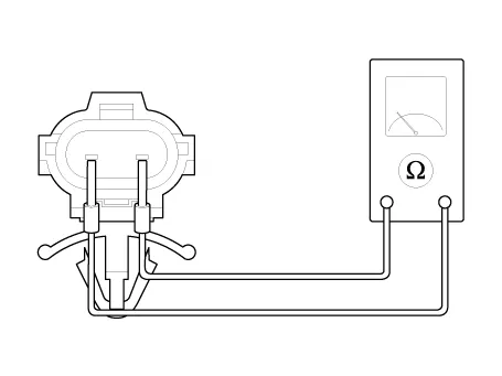
| 3. | Check
the resistance of ambient temperature sensor between terminals 1 and 2
whether it is changed by changing of the ambient temperature.
Specification
|
| Replacement |
| 1. | Disconnect the negative (-) battery terminal. |
| 2. | Remove the engine room under cover.
G 1.0 MPI-KAPPA (Refer to Engine Mechanical System - "Engine Room Under Cover")
G 1.2 MPI-GAMMA (Refer to Engine Mechanical System - "Engine Room Under Cover")
F 1.0 KAPPA FFV (Refer to Engine Mechanical System - "Engine Room Under Cover")
G 1.0 T-GDI KAPPA (Refer to Engine Mechanical System - "Engine Room Under Cover")
|
| 3. | Disconnect the connector (A) and then remove the ambient temperature sensor (B).
|
| 4. | Install in the reverse order of removal. |
- Heater
- Blower
- Blower Unit
- Blower Motor
- Blower Resistor (Manual)
- Power Mosfet
- Climate Control Air Filtar
- Intake Actuator
- Controller
Repair procedures Inspection Front Washer Motor 1.With the washer motor connected to the reservoir tank, fill the reservoir tank with water. • Before filling the reservoir tank with water, check the filter for foreign material or contamination.
Other information:
Kia Picanto (JA) 2017-2026 Service & Repair Manual: Rear Glass Defogger Printed Heater
Repair procedures Inspection • Wrap tin foil around the end of the voltmeter test lead to prevent damaging the heater line. Apply pressure on the tin foil with hand and move the tin foil along the grid line to check for open circuits.
Kia Picanto (JA) 2017-2026 Service & Repair Manual: Front Washer Motor
Repair procedures Inspection Front Washer Motor 1.With the washer motor connected to the reservoir tank, fill the reservoir tank with water. • Before filling the reservoir tank with water, check the filter for foreign material or contamination.
Categories
- Manuals Home
- Kia Picanto Owners Manual
- Kia Picanto Service Manual
- Suspension System
- Front Disc Brake
- Features of your vehicle
- New on site
- Most important about car
