Kia Picanto (JA): Heater / Heater Unit
Components and components location
| Component Location |
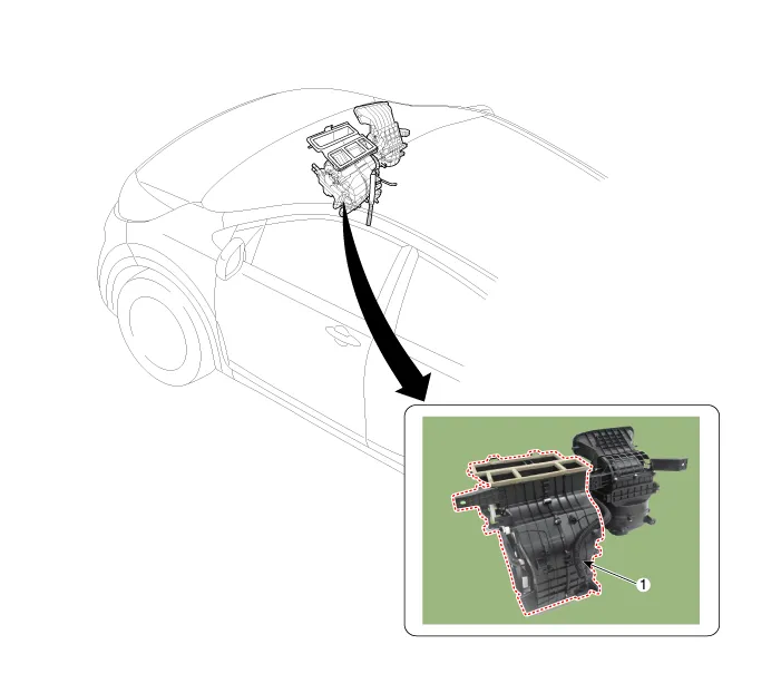
| 1. Heater Unit |
| Components |
| [LH] |
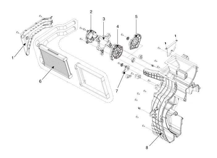
| 1. Heater Core Cover 2. Mode Control Actuator 3. Mode Control Actuator braket 4. Mode Cam | 5. Mode Cam 6. Heater Core 7. Door Cover [Floor] 8. Heater Case [LH] |
| [RH] |
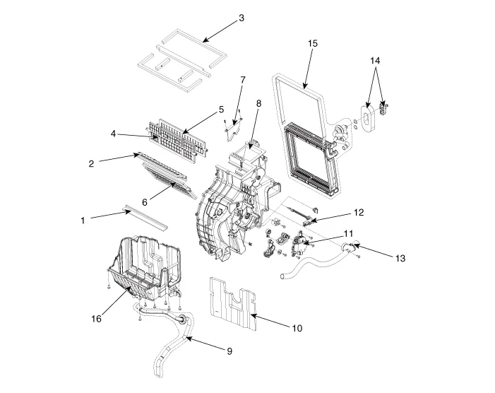
| 1. Lower Insulation 2. Floor Door Assembly 3. Seal 4. Vent Door Assembly 5. Defogging Door Assembly 6. Temperature Door Assembly 7. Vent Guide 8. Heater Case [RH] | 9. Drain Hose 10. Anti Noise Pad 11. Temperature Control Actuator 12. Evaporator Temperature Sensor 13. Aspirator Hose Assembly 14. Evaporator Hose Assembly 15. Evaporator Assembly 16. Heater Case [Lower] |
Repair procedures
| Replacement |
| 1. | Disconnect the negative (-) battery terminal. |
| 2. | Recover the refrigerant with a recovery/ recycling/ charging station. |
| 3. | When the engine is cool, drain the engine coolant from the radiator. |
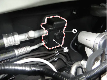
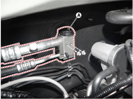
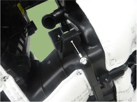
| 4. | Loosen the mounting nut and then remove the expansion valve cover (A).
|
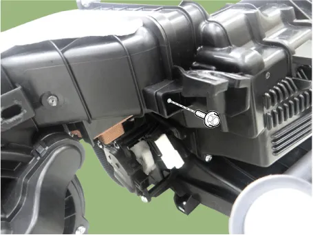
| 5. | Remove the bolts and the expansion valve (A) from the evaporator core.
|

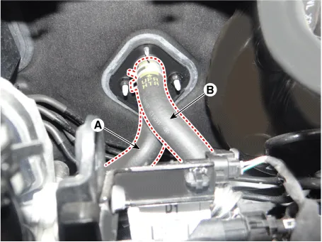
| 6. | Disconnect the inlet (A) and outlet (B) heater hoses from the heater unit.
|
| 7. | Remove the cowl top cover.
(Refer to Body - "Cowl Top Cover")
|
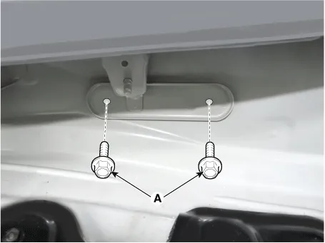
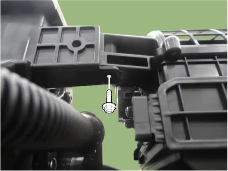
| 8. | Loosen the cowl cross member mounting bolts (A).
|
| 9. | Remove the front seat assembly.
(Refer to Body - "Front Seat Assembly")
|
| 10. | Remove the floor console assembly.
(Refer to Body - "Floor Console Assembly")
|
| 11. | Remove both sides of the front pillar trim.
(Refer to Body - "Front Pillar Trim")
|
| 12. | Remove both sides of the cowl side trim.
(Refer to Body - "Cowl Side Trim")
|
| 13. | Remove the crash pad lower panel.
(Refer to Body - "Crash Pad Lower Panel")
|
| 14. | Remove the steering column shroud lower panel.
(Refer to Body - "Steering Column Shroud Panel")
|
| 15. | Remove the steering wheel.
(Refer to Steering System - "Steering Wheel")
|
| 16. | Remove the multifunction switch.
(Refer to Body Electrical System - "Multifunction Switch")
|
| 17. | Lower the steering column after loosening the mounting bolts.
(Refer to Steering System - "Steering Column and Shaft")
|
| 18. | Remove the front door scuff trim.
(Refer to Body - "Door Scuff Trim")
|
| 19. | Remove the sheft lever assembly.
(Refer to Automatic Transaxle System - "Sheft Lever")
|
| 20. | Disconnect the airbag control module (SRSCM) connector (A).
|
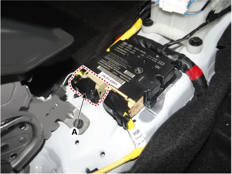
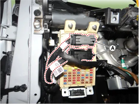
| 21. | Disconnect the passenger compartment junction box connectors (A).
|
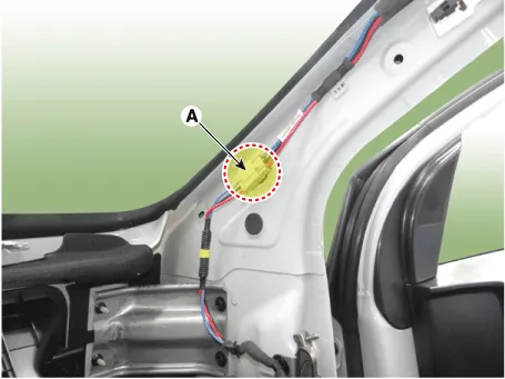
| 22. | Disconnect the connector (A) and the mounting clips in the front pillar.
|
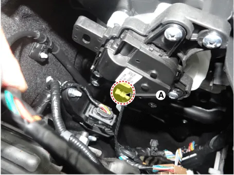
| 23. | Disconnect the multi box connectors (A).
|
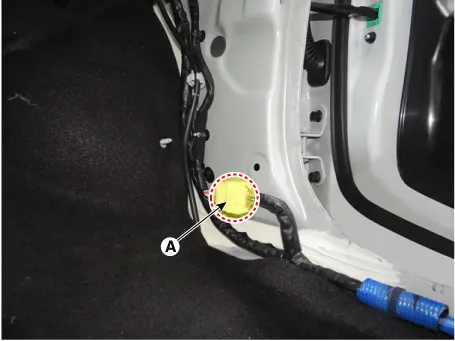
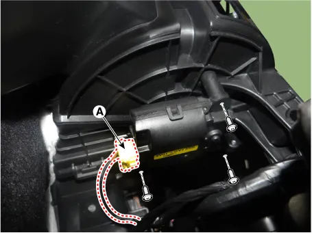
| 24. | Remove the drain hose (A).
|

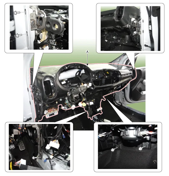
| 25. | After loosening the bolts, remove the main crash pad and cowl cross bar assembly (A) altogether.
|
| 26. | Disconnect the heater & blower unit connectors.
|
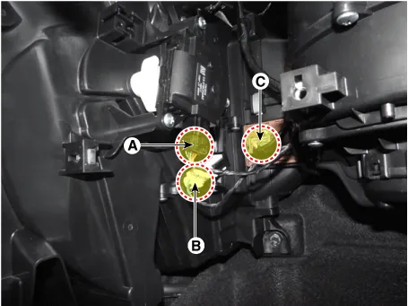
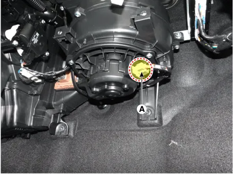
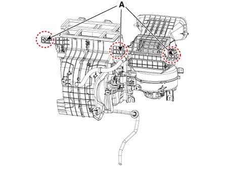
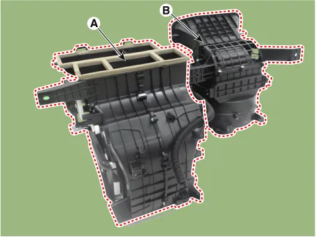
| 27. | Remove the blower unit (B) from the heater unit (A) after loosening the screws.
|
| 28. | Install in the reverse order of removal. |
Components and components location Component Location 1. Temerature Control Actuator Description and operation Description 1.
Other information:
Kia Picanto (JA) 2017-2026 Service & Repair Manual: Rear Glass Defogger
C
Kia Picanto (JA) 2017-2026 Service & Repair Manual: Blower Unit
Components and components location Component Location 1. Blower Unit Components 1. Intake Actuator 2. Intake Case [Lower] 3. Air Filter 4. FET 5. Resister 6. Intake Seal 7. Intake Case [Upper] 8. Intake Door Assembly 9. Anti Noise Pad 10.
Categories
- Manuals Home
- Kia Picanto Owners Manual
- Kia Picanto Service Manual
- Coolant
- Timing Chain
- Charging System
- New on site
- Most important about car

Copyright © 2026 www.kpicanto.com - 0.0268