Kia Picanto (JA): Seat Electrical / Seat Heater
Components and components location
| Component Location |
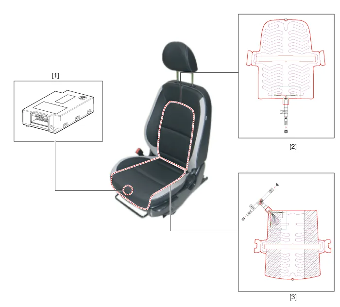
| 1. Seat heater unit 2. Front seat back heater | 3. Front seat cushion heater |
Schematic diagrams
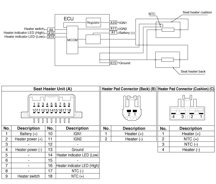
| Circuit Diagram |
Repair procedures
| Inspection |
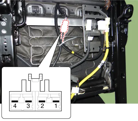
| 1. | Check for continuity and measure the resistance between terminals No 1 and No 4.
|
| 2. | Operate
the seat heater after connecting the connector, and then check the
thermostat by measuring the temperature of seat surface.
|
| Removal |
| 1. | Disconnect the negative (-) battery terminal. |
| 2. | Remove the front seat assembly.
(Refer to Body - "Front Seat Assembly")
|
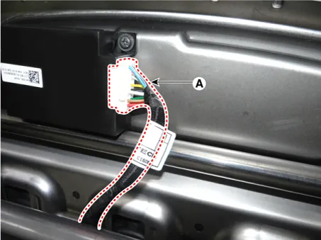
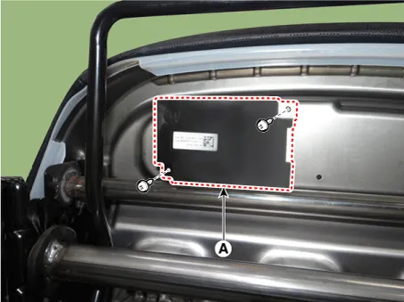
| 3. | Disconnect the seat heater unit connector (A).
|
| 4. | Remove the seat heater unit (A) after loosening the mounting screws.
|
| Installation |
| 1. | Install the seat heater unit and connecting the connector. |
| 2. | Install the front seat assembly. |
| 3. | Connect the negative (-) battery terminal. |
Components and components location Components 1. Driver side seat heater switch 2. Passenger side seat heater switch Schematic diagrams Circuit Diagram Repair procedures Removal 1.
Other information:
Kia Picanto (JA) 2017-2026 Service & Repair Manual: Emergency Call (eCall) Button
Components and components location Component Repair procedures Removal 1. Disconnect the negative (-) battery terminal. 2. Using a screwdriver or remover, separate the map lamp lens (A) from the map lamp. 3. Remove the map lamp (A) after loosening the screws.
Kia Picanto (JA) 2017-2026 Service & Repair Manual: Climate Control Air Filtar
Description and operation Description This has particle filter which eliminates foreign materials and odor. The particle filter includes odor filter as well as conventional dust filter to ensure comfortable interior environment. Repair procedures Replacement 1.
Categories
- Manuals Home
- Kia Picanto Owners Manual
- Kia Picanto Service Manual
- Fuel Delivery System
- Thermostat
- Body Electrical System
- New on site
- Most important about car
