Kia Picanto (JA): Windshield Wiper/Washer / Front Washer Motor
Repair procedures
| Inspection |
| 1. | With the washer motor connected to the reservoir tank, fill the reservoir tank with water.
|

| 2. | Connect positive (+) battery cables to terminal 1 and negative (-) battery cables to terminal 2 respectively. |
| 3. | Check that the motor operates normally and the washer motor runs and water sprays from the front nozzles. |
| 4. | If they are abnormal, replace the washer motor. [Front & Rear washer]
|

| Removal |
| 1. | Disconnect the negative (-) battery terminal. |
| 2. | Remove the engine room under cover.
G 1.0 MPI (Refer to Engine Mechanical System - "Engine Room Under Cover")
G 1.2 MPI (Refer to Engine Mechanical System - "Engine Room Under Cover")
|
| 3. | Remove the front wheel guard [RH].
(Refer to Body - "Front Wheel Guard")
|
| 4. | Drain the washer fluid to less than 650 cc. |
| 5. | Disconnect the washer hose (A) and washer motor connector (B). |
| 6. | Remove the front washer motor (C).
|

| 1. | Disconnect the negative (-) battery terminal. |
| 2. | Remove the front bumper assembly.
(Refer to Body - "Front Bumper Assembly")
|
| 3. | Remove the right headlamp.
(Refer to Lighting System - "Headlamps")
|
| 4. | Remove the front bumper side bracket (A) after loosening the mounting bolts.
|
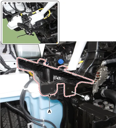
| 5. | Remove the wiring harness mounting clips (A) from the reservoir tank.
|

| 6. | Drain the washer fluid to less than 650 cc. |
| 7. | Disconnect the washer hoses (A) and connector (B). |
| 8. | Remove the reservoir tank (C) after loosening the bolts.
|


| Installation |
| 1. | If necessary, clean the washer motor filter.
|
| 2. | Install the front washer motor. |
| 3. | Connect the front washer motor connector. |
| 4. | Install the front wheel guard [RH]. |
| 5. | Install the engine room under cover. |
| 6. | Connect the negative (-) battery terminal. |
| 1. | If necessary, clean the washer motor filter.
|
| 2. | Install the reservoir tank. |
| 3. | Install the washer motor hose and connectors. |
| 4. | Install the wiring harness mounting clips from the reservoir tank. |
| 5. | Install the front bumper side bracket. |
| 6. | Install the right headlamp. |
| 7. | Install the front bumper assembly. |
| 8. | Connect the negative (-) battery terminal. |
Components and components location Component Location 1. Cap 2. Nut 3. Wiper arm & blade 4. Cowl top cover 5. Bolt 6. Wiper motor & linkage assembly 7.
Specifications Specification Air conditioner Item Specification Compressor Type 5VSe09(Variable Dispacement Swashplate) 5VS09 Oil type & Capacity FD46XG(PAG) 100±10g Pulley type POLY V RIBBED BEIT 6PK Displacement 90cc/rev Condenser Heat rejection 9,890 -3% kcal/hr A/C Pressure transducer The method to measure the pressure DUEL Switch Voltage= 0.
Other information:
Kia Picanto (JA) 2017-2026 Service & Repair Manual: Power Door Mirror Actuator
Components and components location Components 1. Side repeater lamp Repair procedures Inspection 1. Disconnect the negative (-) battery terminal. 2. Remove the front door quadrant inner cover (A). 3. Disconnect the tweeter speaker connector (A).
Kia Picanto (JA) 2017-2026 Service & Repair Manual: Rear Parking Assist System
Specifications Specification Item Specification Ultrasonic sensor Voltage rating DC 12V Detecting range 11.8 - 39.3 in (30 - 100 cm) Operation voltage DC 9 - 16 V Operation current 60mA Max.
Categories
- Manuals Home
- Kia Picanto Owners Manual
- Kia Picanto Service Manual
- Charging System
- Timing Chain
- Thermostat
- New on site
- Most important about car
