Kia Picanto (JA): Heater / Mode Control Actuator
Components and components location
| Component Location |
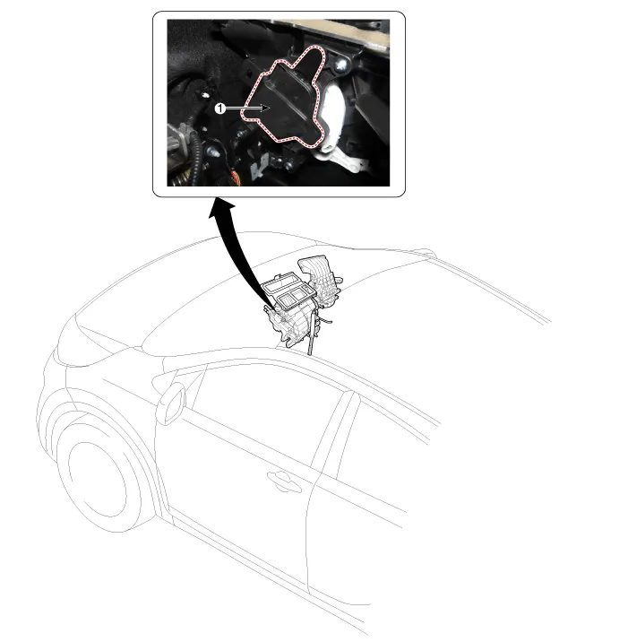
| 1. Mode Control Actuator |
Description and operation
| Description |
Repair procedures
| Inspection |
| 1. | Ignition "OFF” |
| 2. | Disconnect the connector of mode control actuator. |
| 3. | 3.
Verify that the mode control actuator operates to the defrost mode when
connecting 12V to the terminal 3and grounding terminal 4. |
| 4. | Verify that the mode control actuator operates to the vent mode when connecting in the reverse.
|

| 5. | Check the voltage between terminals 6 and 7.
It will feedback current position of actuator to controls. |
| 6. | If the measured voltage is not specification, substitute with a known-good mode control actuator and check for proper operation. |
| 7. | If the problem is corrected, replace the mode control actuator. |
| Replacement |
| 1. | Disconnect the negative (-) battery terminal. |
| 2. | Remove the main crash pad assembly.
(Refer to Body - "Main Crash Pad Assembly")
|
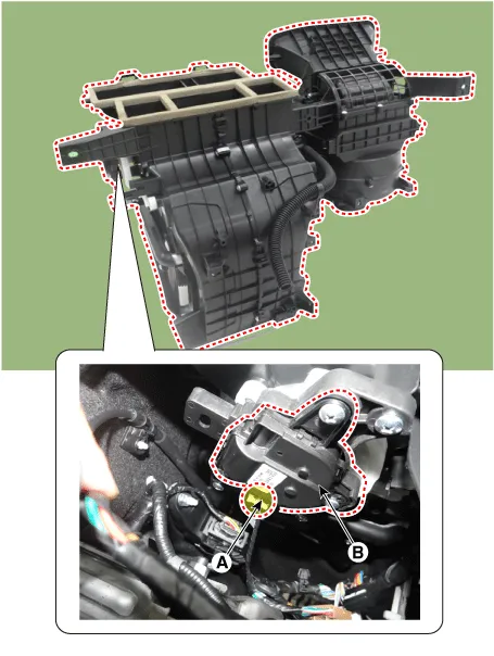
| 3. | Disconnect the connector (A) and then remove the mode control actuator (B) after loosening the mounting screws
|
| 4. | Install in the reverse order of removal. |
Components and components location Component Location 1. Temerature Control Actuator Description and operation Description 1.
Repair procedures Replacement 1.Disconnect the negative (-) battery terminal. 2.Remove the heater unit. (Refer to Heater - "Heater Unit") 3.
Other information:
Kia Picanto (JA) 2017-2026 Service & Repair Manual: Button Engine Start System
Components and components location Component Location 1. Body control module (BCM) 2. Smart key unit (SMK) 3. Interior antenna 1 4. Interior antenna 2 5. FOB key 6. Start Stop Button (SSB) 7. Door handle & door antenna 8. Bumper antenna 9.
Kia Picanto (JA) 2017-2026 Service & Repair Manual: Lighting System
Specifications Specification Item Type Bulb Watt (W) Front Headlamp Halogen (Position lamp) Low/High H4 LL 55/60 Turn signal lamp PY21WLL 21 Position lamp W5WLL 5 Halogen (Position lamp + DRL) Low/High HB3 (9005HL+) 60 Turn signal lamp LED LED Po
Categories
- Manuals Home
- Kia Picanto Owners Manual
- Kia Picanto Service Manual
- Engine Control / Fuel System
- Front Disc Brake
- Battery
- New on site
- Most important about car
