Kia Picanto (JA): Blower / Climate Control Air Filtar
Description and operation
| Description |
Repair procedures
| Replacement |
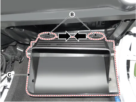
| 1. | Remove the stopper (A) from the glove box.
|

| 2. | Disconnect the pins (B) and then remove the glove box (C).
|
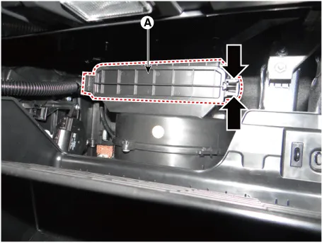
| 3. | Remove the filter cover (A) by pressing the knob.
|
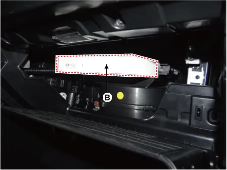
| 4. | Replace
the air filter (B) according to the replacement cycle on the user
manual. When replacing it, mind the direction of the air filter.
|

| 5. | Install in the reverse order of removal. |
Repair procedures Inspection 1.Ignition "ON" 2.Manually operate the control switch and measure the voltage of blower motor. 3.Select the control switch to raise voltage until high speed.
Components and components location Component Location 1. Intake Actuator Description and operation Description 1. The intake actuator is located at the blower unit.
Other information:
Kia Picanto (JA) 2017-2026 Service & Repair Manual: Electro Chromic Inside Rear View Mirror
Components and components location Components Description and operation Description The ECM (Electro Chromatic inside rear view Mirror) is one that automatically dims to protect the driver’s eyes when it senses light reflecting from the car behind.
Kia Picanto (JA) 2017-2026 Service & Repair Manual: Rear Combination Lamp
Repair procedures Removal 1.Disconnect the negative (-) battery terminal. 2.Remove the rear combination lamp (A) after loosening the screws. 3.Remove the rear combination lamp packing (A). 4.Disconnect the rear combination lamp connector (A).
Categories
- Manuals Home
- Kia Picanto Owners Manual
- Kia Picanto Service Manual
- Automatic Transaxle Fluid
- Normal Condition
- To set cruise control speed
- New on site
- Most important about car
