Kia Picanto (JA): Controller / Heater & A/C Control Unit(Manual)
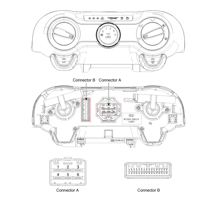
Components and components location
| Components |
| [NON ISG] |
|
No.
|
Connector A
|
Connector B
|
| 1 | Low | Battery |
| 2 | Common | Illumination (+) |
| 3 | Ground | HTD |
| 4 | Middle (Low) | ISG Battery |
| 5 | Middle (High) | - |
| 6 | High | Detent out (-) |
| 7 | - | |
| 8 | Sensor REF (+5V) | |
| 9 | Intake actuator (FRE) | |
| 10 | Intake actuator (REC) | |
| 11 | Intake actuator Feedback | |
| 12 | PAB On signal | |
| 13 | PAB Off signal | |
| 14 | Ground | |
| 15 | Sensor ground | |
| 16 | Illumination (-) | |
| 17 | IGN2 | |
| 18 | IGN1 | |
| 19 | PAB IGN1 | |
| 20 | Ambient sensor (+) | |
| 21 | Evaporator sensor (+) | |
| 22 | MAX Blower on signal | |
| 23 | Seat belt reminder | |
| 24 | Rear left seat belt reminder | |
| 25 | Rear center seat belt reminder | |
| 26 | Rear right seat belt reminder | |
| 27 | - | |
| 28 | C_CAN (High) | |
| 29 | C_CAN (Low) | |
| 30 | Rear deffog switch | |
| 31 | Blower on signal to Common | |
| 32 | Ground |
Repair procedures
| Replacement |
| 1. | Disconnect the negative (-) battery terminal. |
| 2. | Remove the floor console assembly.
(Refer to Body - "Floor Console Assembly")
|
| 3. | Remove the crash pad lower panel.
(Refer to Body - "Crash Pad Lower Panel")
|
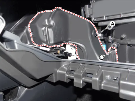
| 4. | Remove the driver's side shower duct (A) after loosening the screw.
|

| 5. | Disconnect the mode control cable (A).
|

| 6. | Remove the glove box housing.
(Refer to Body - "Glove Box Housing")
|
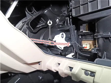
| 7. | Remove the passenger's side shower duct (A) after loosening the screw.
|
| 8. | Disconnect the temperature control cable (A).
|
| 9. | After loosening the mounting screws, remove the A/C & heater controller unit (A).
|
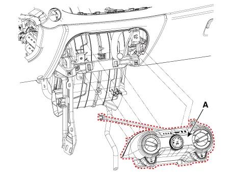
| 10. | Disconnect the A/C & heater controller connectors (A).
|

| 11. | Install in the reverse order of removal. |
Components and components location Components Control Panel Connector pin function No. Connector A Connector B 1 Battery PAB IGN1 2 ISG Battery (+) PAB On signal 3 Illumination (+) PAB Off signal 4 Sensor REF (+5V) - 5 Mode control actuator Feedback - 6 Temperature control actuator Feedback - 7 Intake actuator Feedback - 8 Evaporator sensor (+) - 9 Ambient sensor (+) - 10 Driver mode control actuator (Vent) - 11 Driver mode control actuator (DEF) Seat belt reminder 12 Temperature control actuator (Cool) Rear left seat belt reminder 13 Temperature control actuator (Warm) Rear center seat belt reminder 14 Intake actuator (FRE) Rear right seat belt reminder 15 Intake actuator (REC) - 16 HTD Ground 17 Rear defog switch 18 - 19 - 20 Illumination (-) 21 IGN2 22 IGN1 23 Blower motor (+) 24 Photo sensor (-) 25 - 26 - 27 - 28 - 29 - 30 - 31 Detent out (-) 32 - 33 C_CAN (High) 34 C_CAN (Low) 35 FET (Drain Feedback) 36 FET (Gate) 37 ECV (+) 38 ECV (-) Repair procedures Self Diagnosis 1.
Other information:
Kia Picanto (JA) 2017-2026 Service & Repair Manual: High Mounted Stop Lamp
Repair procedures Removal 1. Disconnect the negative (-) battery terminal. 2. Open the tailgate. 3. Loosen the high mounted stop lamp mounting nuts (A). 4. Disconnect the washer nozzle (A) and high mounted stop lamp connector (B). 5. Remove the high mounted stop lamp (C).
Kia Picanto (JA) 2017-2026 Service & Repair Manual: Power Door Mirrors
C
Categories
- Manuals Home
- Kia Picanto Owners Manual
- Kia Picanto Service Manual
- Cylinder Head
- Automatic Transaxle Fluid
- Engine Mechanical System
- New on site
- Most important about car
