Kia Picanto (JA): Emission Control System
Specifications
| Specifications |
|
Item
|
Specification
|
| Coil Resistance (Ω) | 18.5 - 22.5 [23°C(73.4°F)] |
| Tightening Torques |
|
Item
|
kgf·m
|
N·m
|
lb·ft
|
| Purge Control Solenoid Valve (PCSV) bracket mounting bolt | 1.0 - 1.2 | 9.8 - 11.8 | 7.2 - 8.7 |
| Positive Crankcase Ventilation (PCV) Valve | 0.19 - 0.29 | 1.89 - 2.84 | 1.40 - 2.09 |
| Canister installation bolt | 0.3 - 0.6 | 3.0 - 6.0 | 2.1 - 4.3 |
Components and components location
| Components Location |
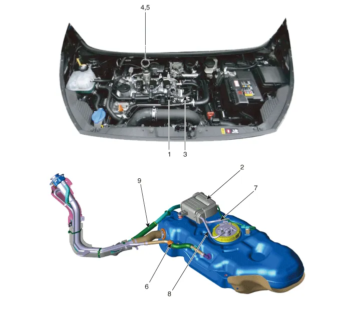
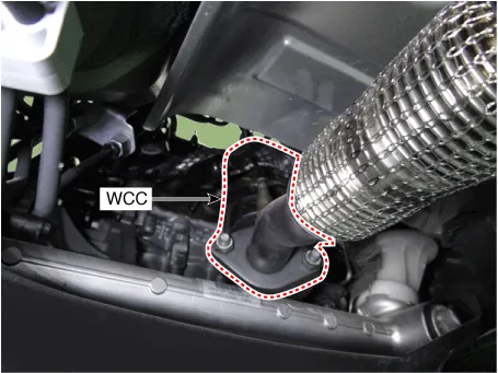
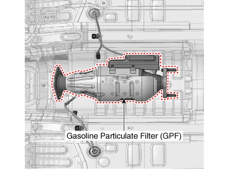
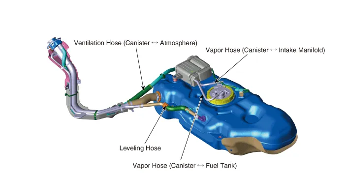
| 1. PCV valve 2. Canister 3. Purge control solenoid valve (PCSV) 4. Catalytic converter (WCC) 5. Gasoline Particulate Filter (GPF) | 6. Leveling Hose 7. Vapor Tube (Canister ↔ Intake Manifold) 8. Vapor Hose (Canister ↔ Fuel Tank) 9. Ventilation Hose (Canister ↔ Atmosphere) |
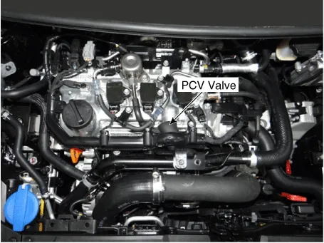
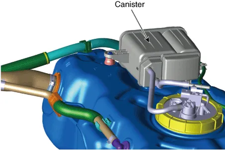
| 1. PCV valve | 2. Canister |
|
|
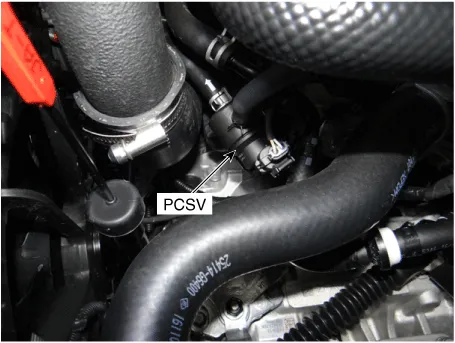
| 3. Purge Control Solenoid Valve (PCSV) | 4. Catalytic Converter (WCC) |
|
|
| 5. Gasoline Particulate Filter (GPF) | |
| |
| 6. Leveling Hose 7. Vapor Tube ( Canister ↔ Intake Manifold) 8. Vapor Hose (Canister ↔ Fuel Tank) 9. Ventilation Hose (Canister ↔ Atmosphere) | |
| |
Description and operation
| Description |
| • | The
Crankcase Emission Control System prevents blow-by gas from releasing
into the atmosphere. This system recycles gas back into the intake
manifold (Closed Crankcase Ventilation Type). |
| • | The
Evaporative Emission Control System prevents evaporative gas from
releasing into the atmosphere. This system burns gas at appropriate
engine operating condition after gathering it in the canister. |
| • | The
Exhaust Emission Control System converts the three pollutants
[hydrocarbons (HC), carbon monoxide (CO), and oxides of nitrogen (NOx)]
into harmless substances by using the 3-way catalytic converter. |
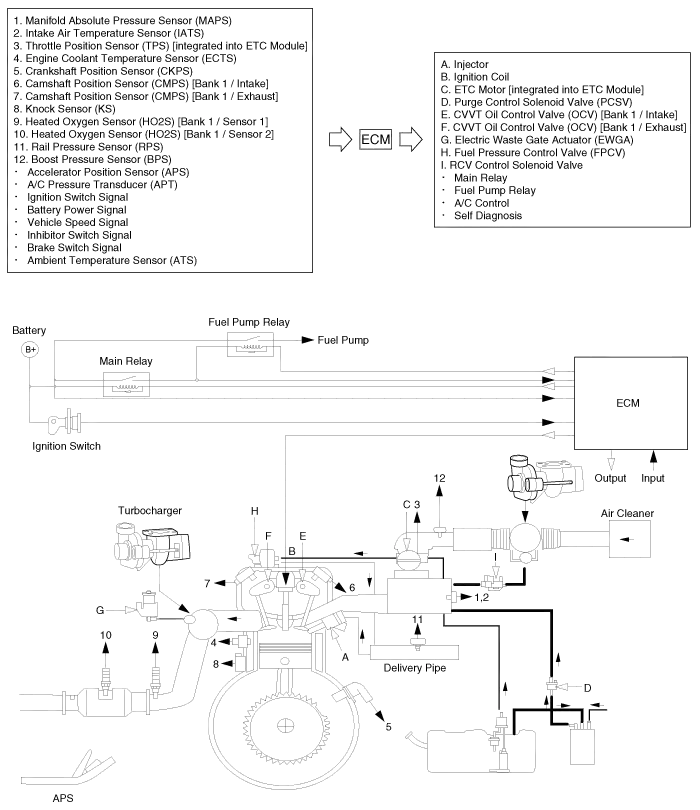
Schematic diagrams
| Schematic Diagram |
Troubleshooting
| Troubleshooting |
|
Symptom
|
Suspect area
|
| Unable or hard to start engine | Vapor hose damaged or disconnected |
| Engine hard to start | Malfunctioning Purge Control Solenoid Valve |
| Rough idle or engine stalling | Vapor hose damaged or disconnected |
| Malfunctioning PCV valve | |
| Rough idle | Malfunctioning Evaporative Emission Control System |
| Excessive oil consumption | Positive crankcase ventilation line clogged |
Components and components location Components 1. Right Remote Control Switch (Cruise+Trip Computer) Schematic diagrams Circuit Diagram [Trip (2 Button) + SEG LCD Cluster] [Trip (2 Button) + ACC + Cruise] [Trip (2 Button) + ACC + Cruise + SLD] [Trip (4 Button) + DOT&TFT LCD Cluster] [Trip (4 Button) + ACC + Cruise] [Trip (4 Button) + ACC + Cruise + SLD] Repair procedures Removal 1.
Schematic diagrams Schematic Diagram Repair procedures Inspection 1. After disconnecting the vapor hose from the PCV valve, remove the PCV valve.
Other information:
Kia Picanto (JA) 2017-2026 Service & Repair Manual: Sunroof
C
Kia Picanto (JA) 2017-2026 Service & Repair Manual: Heater Unit
Components and components location Component Location 1. Heater Unit Components [LH] 1. Heater Core Cover 2. Mode Control Actuator 3. Mode Control Actuator braket 4. Mode Cam 5. Mode Cam 6. Heater Core 7. Door Cover [Floor] 8. Heater Case [LH] [RH] 1.
Categories
- Manuals Home
- Kia Picanto Owners Manual
- Kia Picanto Service Manual
- Coolant
- Engine Control / Fuel System
- Suspension System
- New on site
- Most important about car
