Kia Picanto (JA): Exhaust Emission Control System / GPF (Gasoline Particulate Filter)
Description and operation
| Description |
Repair procedures
| GPF Regeneration |
|

| – | Engine coolant temperature : about 70°C |
| – | Engine at idle |
| – | P-range (A/T) or Neutral (M/T) |
| – | Normal battery voltage |
| – | Electrical fully load ON (A/C ON if equipped, Blower ON with maximum speed, Head Lamp ON, Wiper ON, Other Lamps ON, etc.). |
| 1. | Turn ignition switch OFF. |
| 2. | Connect a KDS to Data Link Connector (DLC). |
| 3. | Turn ignition switch ON. |
| 4. | Select "Vehicle, Model year, Engine, System". |
| 5. | Start engine at idle and P-range (A/T) or neutral (M/T). |
| 6. | Apply
electrical fully load to the vehicle (A/C ON, Blower ON with maximum
speed, Head Lamp ON, Wiper ON, and Other Lamps ON, etc.). |
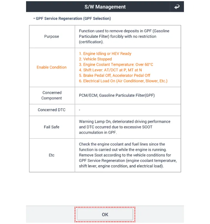
| 7. | Select "Vehicle S/W Management". |
| 8. | Select "GPF Service Regeneration".
|

| Removal & Installation |
| 1. | Turn ignition switch OFF and disconnect the battery negative (-) terminal. |
| 2. | Remove the exhaust gas temperature sensor (EGTS) #1, #2.
(Refer to Engine Control / Fuel System - "Exhaust Gas Temperature Sensor (EGTS)")
|
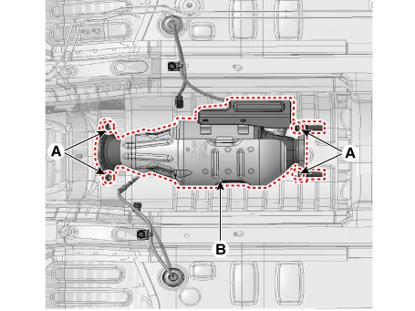
| 3. | Remove the GPF (C) after removing the installation nuts.
|
| 4. | Install in the reverse order of removal.
|

| Replacement |
|
| 1. | Turn ignition switch OFF. |
| 2. | Connect a KDS to Data Link Connector (DLC). |
| 3. | Turn ignition switch ON. |
| 4. | Select "Vehicle, Model year, Engine, System". |
| 5. | Start engine at idle and P-range (A/T) or neutral (M/T). |
| 6. | Apply
electrical fully load to the vehicle (A/C ON, Blower ON with maximum
speed, Head Lamp ON, Wiper ON, and Other Lamps ON, etc.). |
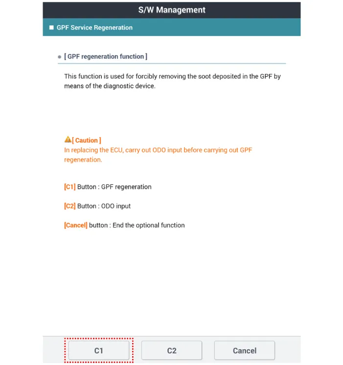
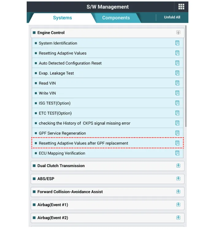
| 7. | Select "Vehicle S/W Management". |
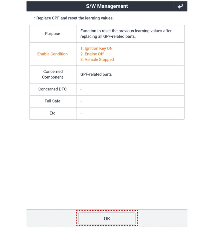
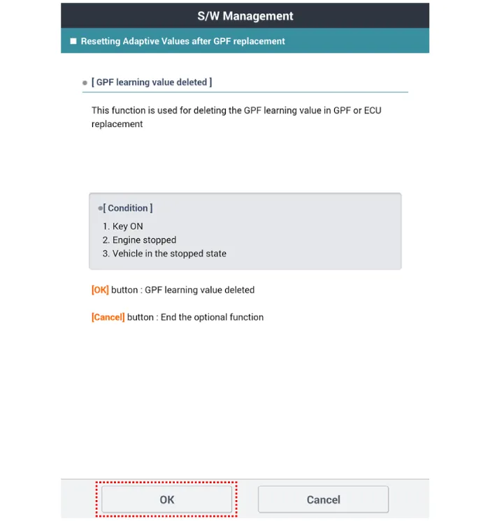
| 8. | Select "Resetting Adaptive Values after GPF replacement".
|
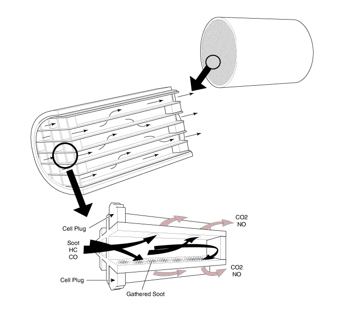
Description and operation Description Exhaust emissions (CO, HC, NOx) are controlled by a combination of engine modifications and the addition of special control components.
Description and operation Description The catalytic converter of the gasoline engine is a three way catalyst. It oxidizes carbon monoxide and hydrocarbons (HC), and separates oxygen from the oxides of nitrogen (NOx).
Other information:
Kia Picanto (JA) 2017-2026 Service & Repair Manual: Headlamp Leveling Actuator
Components and components location Components Repair procedures Removal 1.Disconnect the negative (-) battery terminal. 2.Remove the headlamp assembly. (Refer to Lighting System - "Headlamps") Installation 1.Install the headlamp assembly.
Kia Picanto (JA) 2017-2026 Service & Repair Manual: Blower Motor
Repair procedures Inspection 1. Connect the battery voltage and check the blower motor rotation. 2. If the blower motor voltage is not operated well, substitute with a known-good blower motor and check for proper operation. 3. If the problem is corrected, replace the blower motor.
Categories
- Manuals Home
- Kia Picanto Owners Manual
- Kia Picanto Service Manual
- Charging System
- Engine Mechanical System
- Cooling System
- New on site
- Most important about car
