Kia Picanto (JA): Evaporative Emission Control System / Purge Control Solenoid Valve (PCSV)
Specifications
Item
|
Specification
|
Coil Resistance (Ω)
| 18.5 - 22.5 [23°C(73.4°F)]
|
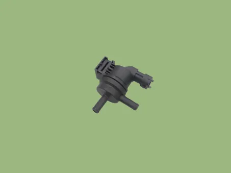
Description and operation
Installed
on the surge tank, the Purge Control Solenoid Valve (PCSV) controls the
passage between the canister and the intake manifold. This solenoid
valve is open when the ECM grounds the valve control line. When the
passage is open (PCSV ON), fuel vapor stored in the canister is
transferred to the intake manifold.
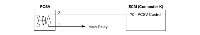
Schematic diagrams

Repair procedures
| 1. | Turn the ignition switch OFF. |
| 2. | Disconnect the PCSV connector. |
| 3. | Measure resistance between the PCSV terminals 1 and 2. |
| 4. | Check that the resistance is within the specification.
Specification: 18.5 - 22.5 [23°C(73.4°F)] |
|
| 1. | Turn the ignition switch OFF and disconnect the battery negative (-) terminal. |
| 2. | Remove the air cleaner.
(Refer to Engine Mechanical System - "Air Cleaner")
|
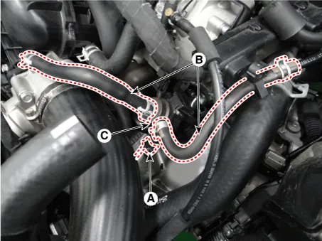
| 3. | Disconnect the purge control solenoid valve connector (A). |
| 4. | Disconnect the vapor hoses (B) from the purge control solenoid valve. |
| 5. | Remove the PCSV (C) by loosening the mounting bolt.
Purge control solenoid valve bracket mounting bolt:
9.8 - 11.8 N·m (1.0 - 1.2 kgf·m, 7.2 - 8.7 lb·ft) |
 |
| •
| Install the component to the specified torques. |
| •
| Note that internal damage may occur when the component is dropped. If the component has been dropped, inspect before installing. |
| •
| Keep foreign materials away from the valve. |
|
| 1. | Install in the reverse order of removal. |
Repair procedures
Removal
1.Turn the ignition switch OFF and disconnect the battery negative (-) terminal.
2.Remove the fuel tank assembly.
(Refer to Fuel System - "Fuel Tank")
3.
Description and operation
Description
A
ratchet tightening device on the threaded fuel filler cap reduces the
chances of incorrect installation, which would seal the fuel filler.
Other information:
Specifications
Specifications
Items
Specifications
Rated voltage DC 12 V Operating temperature range -22 - 176°F (-30 - 80°C) Rated load Washer Washer : 6A (Motor load)
Components and components location
Component
1 .
Repair procedures
Replacement
1.Disconnect the negative (-) battery terminal.
2.Remove the heater unit.
(Refer to Heater - "Heater Unit")
3.Remove the heater core cover (A) after loosening the mounting screws.
4.Pull out the heater core (A) from the heater unit.

