Kia Picanto (JA): Cruise Control System / Cruise Control Switch
Components and components location
| Components |
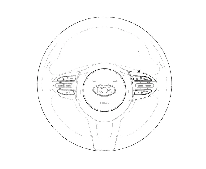
| 1. Right Remote Control Switch (Cruise+Trip Computer) |
Schematic diagrams
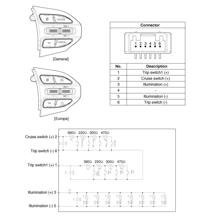
| Circuit Diagram |

| [Trip (2 Button) + SEG LCD Cluster] |

| [Trip (2 Button) + ACC + Cruise] |

| [Trip (2 Button) + ACC + Cruise + SLD] |

| [Trip (4 Button) + DOT&TFT LCD Cluster] |

| [Trip (4 Button) + ACC + Cruise] |
| [Trip (4 Button) + ACC + Cruise + SLD] |

Repair procedures
| Removal |
| 1. | Disconnect the negative (-) battery terminal. |
| 2. | Remove the steering wheel assembly.
(Refer to Steering System - "Steering Wheel")
|
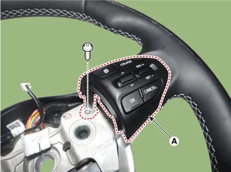
| 3. | Remove the steering wheel remote control (A) after loosening the mounting screws.
|

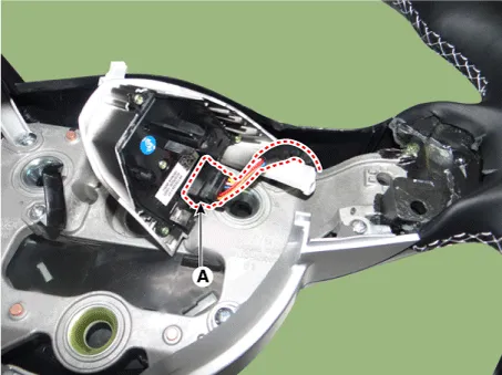
| 4. | Disconnect the steering wheel remote control connector (A).
|
| Installation |
| 1. | Connect the steering wheel remote control connector. |
| 2. | Install the steering wheel remote control. |
| 3. | Install the steering wheel and driver airbag module. |
| 4. | Connect the negative (-) battery terminal. |
| Inspection |
| 1. | Check for resistance between terminals in each switch position.
[RH : Cruise + Trip]
|

Description and operation Description The cruise control system is engaged by the cruise "ON/OFF" main switch located on right of steering wheel column.
Specifications Specifications Purge Control Solenoid Valve (PCSV) ▷ Specification Item Specification Coil Resistance (Ω) 18.
Other information:
Kia Picanto (JA) 2017-2026 Service & Repair Manual: Rear Parking Assist System
Specifications Specification Item Specification Ultrasonic sensor Voltage rating DC 12V Detecting range 11.8 - 39.3 in (30 - 100 cm) Operation voltage DC 9 - 16 V Operation current 60mA Max.
Kia Picanto (JA) 2017-2026 Service & Repair Manual: Seat Heater
Components and components location Component Location 1. Seat heater unit 2. Front seat back heater 3. Front seat cushion heater Schematic diagrams Circuit Diagram Repair procedures Inspection 1.Check for continuity and measure the resistance between terminals No 1 and No 4.
Categories
- Manuals Home
- Kia Picanto Owners Manual
- Kia Picanto Service Manual
- Charging System
- Normal Condition
- Fuel Delivery System
- New on site
- Most important about car
