Kia Picanto (JA): Exhaust Emission Control System / Catalytic Converter
Description and operation
| Description |
Repair procedures
| Removal |
| 1. | Remove the engine room under cover.
(Refer to Engine Mechanical System - "Engine Room Under Cover")
|
| 2. | Drain the engine coolant.
(Refer to Engine Mechanical System - "Coolant")
|
| 3. | Remove the air cleaner assembly.
(Refer to Engine Mechanical System - "Air Cleaner")
|
| 4. | Remove the front muffler.
(Refer to Engine Mechanical System - "Muffler")
|
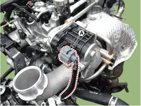
| 5. | Disconnect the electric waste gate actuator (EWGA) extension connector (A).
|
| 6. | Remove the front oxygen sensor.
(Refer to Engine Control / Fuel System - "Heated Oxygen Sensor (HO2S)")
|
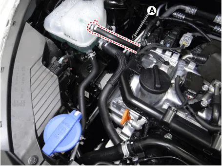
| 7. | Disconnect the water hose (A).
|

| 8. | Disconnect the turbo charger water drain pipe hose (A).
|
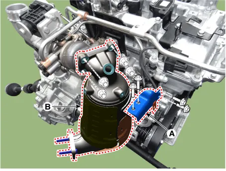
| 9. | Remove the coupler heat protector (A) and water drain pipe (B)
|
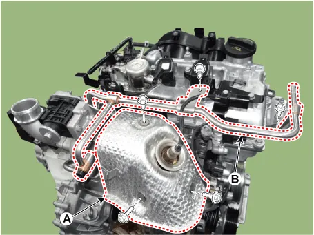
| 10. | Remove the exhaust manifold stay (A).
|
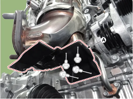
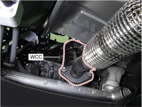
| 11. | Remove the warm-up catalytic converter (WCC) upper stay (A) and then remove the warm-up catalytic converter (WCC) (B).
|
| Installation |
| 1. | Install in the reverse order of removal. |
Description and operation Description The Gasoline Particulate Filter (GPF) system prevents Particulate Matter (PM) from being discharged to the atmosphere and consists of a filter assembly, two Exhaust Gas Temperature Sensors (EGTS).
Description and operation Description Continuous Variable Valve Timing (CVVT) system advances or retards the valve timing of the intake and exhaust valves in accordance with the ECM control signal calculated by the engine speed and load.
Other information:
Kia Picanto (JA) 2017-2026 Service & Repair Manual: Headlamp Leveling Actuator
Components and components location Components Repair procedures Removal 1.Disconnect the negative (-) battery terminal. 2.Remove the headlamp assembly. (Refer to Lighting System - "Headlamps") Installation 1.Install the headlamp assembly.
Kia Picanto (JA) 2017-2026 Service & Repair Manual: Blower Resistor (Manual)
Repair procedures Inspection 1.Measure terminal - to - terminal resistance of blower resistor. 2.measured resistance is not within specification, the blower resistor must be replaced. (After removing the resistor) Replacement 1.Disconnect the negative (-) battery terminal.
Categories
- Manuals Home
- Kia Picanto Owners Manual
- Kia Picanto Service Manual
- Front Disc Brake
- Charging System
- Heating,Ventilation, Air Conditioning
- New on site
- Most important about car
