
Kia Picanto (JA): Crash Pad / Crash Pad Lower Panel
Components and components location
| Component Location |

| 1. Crash pad lower panel |
Repair procedures
| Replacement |
Put on gloves to protect your hands. |

|

| 1. | Remove the crash pad side cover [LH] (A) by using a remover.
|

| 2. | Remove the front door scuff trim (A) by using a remover.
|

| 3. | Remove the hood latch release handle (A) by using a remover.
|

| 4. | Remove the cowl side trim (A) by using a remover.
|
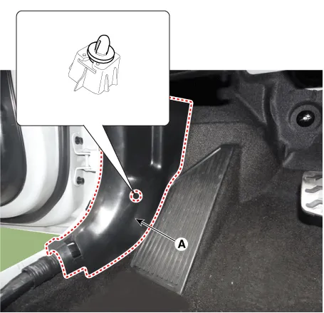
| 5. | Remove the passenger compartment junction box cover (A).
|

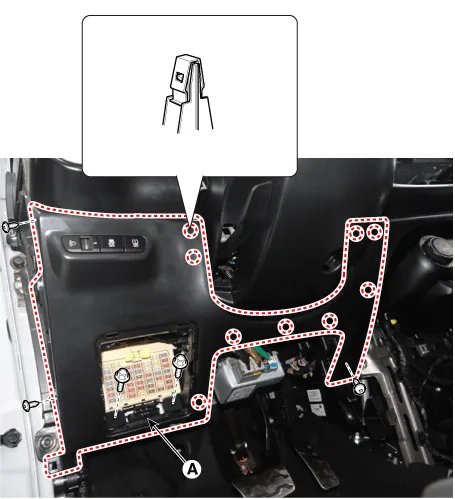
| 6. | Separate the crash pad lower panel (A) after loosening the bolts and screws.
|
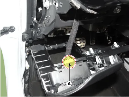
| 7. | Disconnect the crash pad lower side switch connector (A).
|
| 8. | Install in the reverse order of removal.
|
Components and components location Component Location 1. Center fascia panel assembly Repair procedures Replacement Put on gloves to protect your hands.
Components and components location Component Location 1. Glove box housing assembly Repair procedures Replacement Put on gloves to protect your hands.
Other information:
Kia Picanto (JA) 2017-2026 Service & Repair Manual: Rear Washer Switch
Repair procedures Inspection Multifunction Switch Inspection 1. Check for continuity between the terminals in each switch position as shown below. Rear Wiper & Washer Switch[LHD] [RHD] Inspection (With KDS/GDS) 1. In the body electrical system, failure can be quickly diagnosed by using the vehicle diagnostic system (KDS/GDS).
Kia Picanto (JA) 2017-2026 Service & Repair Manual: Heater & A/C Control Unit(Manual)
Components and components location Components [NON ISG] Connector pin function No. Connector A Connector B 1 Low Battery 2 Common Illumination (+) 3 Ground HTD 4 Middle (Low) ISG Battery 5 Middle (High) - 6 High Detent out (-) 7 - 8 Sen
Categories
- Manuals Home
- Kia Picanto Owners Manual
- Kia Picanto Service Manual
- Heating,Ventilation, Air Conditioning
- Cylinder Head
- Normal Condition
- New on site
- Most important about car
