Kia Picanto (JA): Windshield Wiper/Washer / Front Wiper Motor
Components and components location
| Component Location |
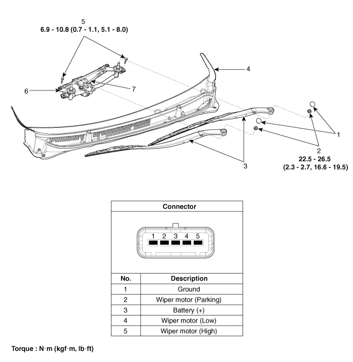
| 1. Cap 2. Nut 3. Wiper arm & blade 4. Cowl top cover | 5. Bolt 6. Wiper motor & linkage assembly 7. Wiper motor connector |
Repair procedures
| Removal |
| 1. | Disconnect the negative (-) battery terminal. |
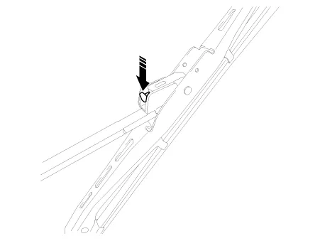
| 2. | If
necessary, release the wiper blade fixing clip by pulling it up and
remove the wiper blade from the inside radius of wiper arm.
|
| 3. | Remove the cowl top cover.
(Refer to Body - "Cowl Top Cover")
|
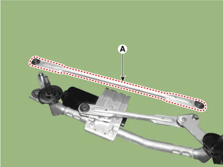
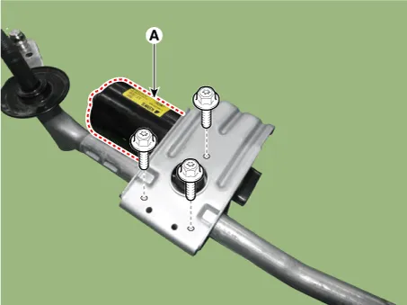
| 4. | Remove the wiper motor & linkage assembly (A) after loosening the mounting bolts.
|

| 5. | Disconnect the wiper motor connector (A).
|

| 6. | Hold the wiper motor crank arm and remove the upper linkage (A).
|


| 7. | Remove the lower linkage (A) from the wiper motor crank arm.
|

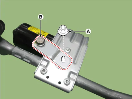
| 8. | Remove the crank arm (B) after loosening a nut (A).
|
| 9. | Remove the wiper motor (A) after loosening the mounting bolts.
|
| Installation |
| 1. | Install the wiper motor. |
| 2. | Install the crank arm.
|
| 3. | Install the lower and upper linkage to the wiper motor crank arm. |
| 4. | Install the wiper motor and linkage assembly and then connect the wiper motor connector.
|
| 5. | Install the cowl top cover. |
| 6. | Install the windshield wiper arm and blade.
|

| 7. | Install the wiper arm and blade to the specified position. Auto stop position (Blade)
|

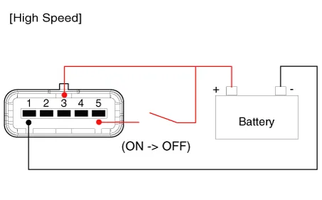
| Inspection |
| 1. | Remove the connector from the wiper motor.
|

| 2. | Attach the positive (+) lead from the battery to terminal 3 and the negative (-) lead to terminal 1.
|

| Inspection (With KDS/GDS) |
| 1. | In the body electrical system, failure can be quickly diagnosed by using the vehicle diagnostic system (KDS/GDS). The diagnostic system(KDS/GDS) provides the following information.
|
| 2. | Select the 'Car model' and the 'Body Control Module (BCM)' to be checked in order to check the vehicle with the tester. |
| 3. | Select the 'Current Data' menu to search the current state of the input/output data.
|

Repair procedures Removal 1.Disconnect the negative (-) battery terminal. 2.Remove the steering column upper and lower shrouds after loosening the screws.
Repair procedures Inspection Front Washer Motor 1.With the washer motor connected to the reservoir tank, fill the reservoir tank with water. • Before filling the reservoir tank with water, check the filter for foreign material or contamination.
Other information:
Kia Picanto (JA) 2017-2026 Service & Repair Manual: Hazard Lamp Switch
Repair procedures Inspection 1.Check for continuity between terminals. If the continuity is not as specified, replace the hazard lamp switch. No. Description No.
Kia Picanto (JA) 2017-2026 Service & Repair Manual: Rear Glass Defogger Printed Heater
Repair procedures Inspection • Wrap tin foil around the end of the voltmeter test lead to prevent damaging the heater line. Apply pressure on the tin foil with hand and move the tin foil along the grid line to check for open circuits.
Categories
- Manuals Home
- Kia Picanto Owners Manual
- Kia Picanto Service Manual
- Clutch Cable
- Timing Chain
- To set cruise control speed
- New on site
- Most important about car
