Kia Picanto (JA): Heater / Temperature Control Actuator
Components and components location
| Component Location |
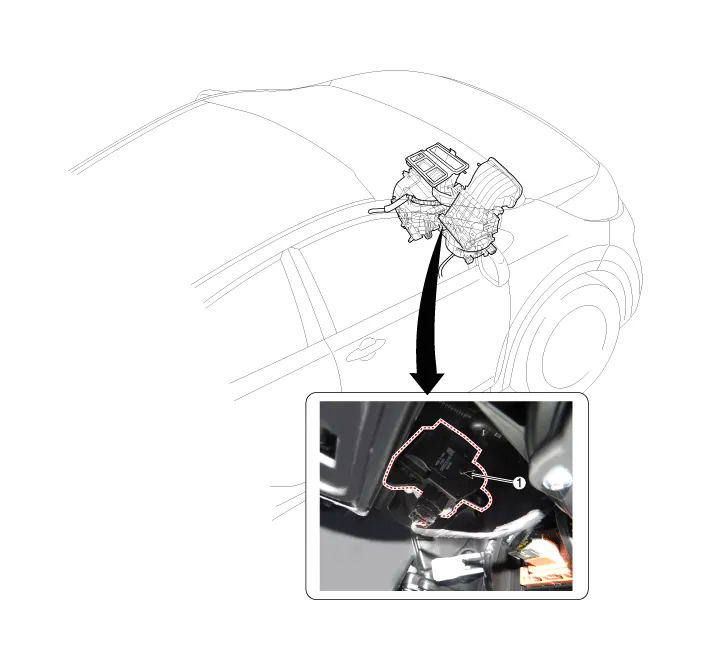
| 1. Temerature Control Actuator |
Description and operation
| Description |
| 1. | Heater unit includes mode control actuator and temperature control actuator. |
| 2. | Temperature
control actuator is located at the heater unit. It regulates the
temperature by the procedure as follows. Signal from control unit
adjusts position of temperature door by operating temperature switch and
then temperature will be regulated by the hot/cold air ratio decided by
position of temperature door |
Repair procedures
| Inspection |
| 1. | Ignition "OFF" |
| 2. | Disconnect the connector of temperature control actuator. |
| 3. | Verify
that the temperature control actuator operates to the hot position when
connecting 12V to the terminal 3 and grounding terminal 4. Verify that the temperature control actuator operates to the cool position when connecting in the reverse.
|

| 4. | Check the voltage between terminals 6 and 7(Drive).
|
| Replacement |
| 1. | Disconnect the negative (-) battery terminal. |
| 2. | Disconnect the connector (A) and then remove the temperature control actuator (B) after loosening the mounting screws.
|
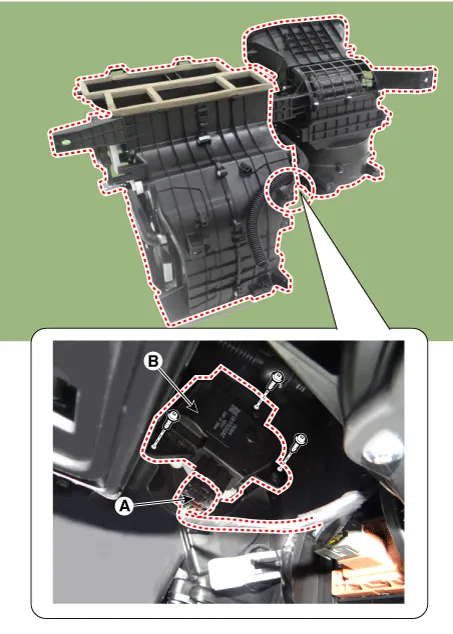
| 3. | Install in the reverse order of removal. |
Components and components location Component Location 1. Heater Unit Components [LH] 1. Heater Core Cover 2. Mode Control Actuator 3.
Components and components location Component Location 1. Mode Control Actuator Description and operation Description The mode control actuator is located at the heater unit.
Other information:
Kia Picanto (JA) 2017-2026 Service & Repair Manual: Ignition Switch Assembly
Repair procedures Inspection 1.Disconnect the key warning switch connector (A) and ignition switch connector (B) from the steering column. 2.Check for continuity between the terminals. 3.If continuity is not specified, replace the switch.
Kia Picanto (JA) 2017-2026 Service & Repair Manual: Power Door Mirror Switch
Components and components location Component Schematic diagrams Circuit Diagram [Folding Mirror Type] [Non-Folding Mirror Type] Repair procedures Inspection 1.Check for continuity between the terminals in each switch position according to the table.
Categories
- Manuals Home
- Kia Picanto Owners Manual
- Kia Picanto Service Manual
- Body Electrical System
- Normal Condition
- Engine Oil and Filter
- New on site
- Most important about car
