Kia Picanto (JA): Power Train / Engine Oil and Filter
Repair procedures
| Inspection |
Be sure that the vehicle is on level ground. |

| 1. | Warm up and stop the engine, and then wait for 5 minutes. |
| 2. | Turn the engine off and wait for a few minutes (about 5 minutes) for the oil to return to the oil pan. |
| 3. | Pull the dipstick out, wipe and re-insert it fully. |
| 4. | Check that the oil level is between the "L" level mark and "F" level mark on the engine oil level gauge. |
| 5. | If the level is low, check for leakage and add oil up to the full level mark.
|

| 1. | Check engine oil for white turbidity or heavy contamination. |
| 2. | If engine oil becomes turbid and white, it is highly probable that it is contaminated with engine coolant. Repair or replace damaged parts. |
| Replacement |
|

| 1. | Park the car on level ground. |
| 2. | Drain the engine oil.
|


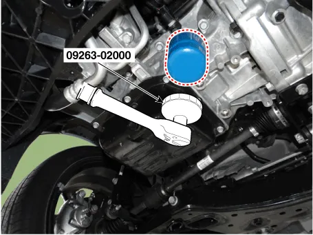
| 3. | Replace the oil filter.
|


| 4. | Install the oil drain plug with a new gasket.
|
| 5. | Fill with new engine oil, after removing the engine oil level gauge.
|
| 6. | Install the oil filler cap. |
| 7. | Start engine and check for oil leaks. |
| 8. | Recheck the engine oil level. |
| 9. | To
reset the service interval to the recommended mileage, refer to the
service mode section in the owner's manual for procedure (if
applicable). |
Repair procedures Inspection 1.Check belt for maintenance and abnormal wear of V-ribbed part. Replace if necessary. • Do not bend, twist or turn the drive belt inside out.
Repair procedures Inspection 1. Visually check the pipes, hangers and connections for severe corrosion, leaks or damage. 2. Check for unusual exhaust sounds or abnormal exhaust fumes.
Other information:
Kia Picanto (JA) 2017-2026 Service & Repair Manual: Rear Combination Lamp
Repair procedures Removal 1.Disconnect the negative (-) battery terminal. 2.Remove the rear combination lamp (A) after loosening the screws. 3.Remove the rear combination lamp packing (A). 4.Disconnect the rear combination lamp connector (A).
Kia Picanto (JA) 2017-2026 Service & Repair Manual: Evaporator Core
Repair procedures Replacement 1.Disconnect the negative (-) battery terminal. 2.Remove the heater unit. (Refer to Heater - "Heater Unit") 3.Remove the Evaporator temperature sensor. (Refer to Air Conditioning System - "Evaporator Temperature Sensor") 4.
Categories
- Manuals Home
- Kia Picanto Owners Manual
- Kia Picanto Service Manual
- Engine Control / Fuel System
- Automatic Transaxle Fluid
- To set cruise control speed
- New on site
- Most important about car
