Kia Picanto (JA): Power Door Mirrors / Power Door Mirror Switch
Components and components location
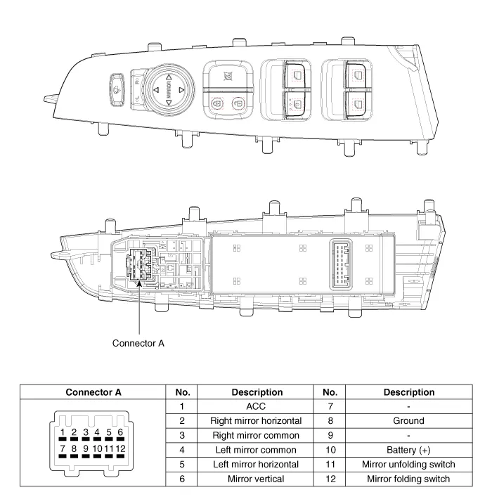
| Component |
Schematic diagrams
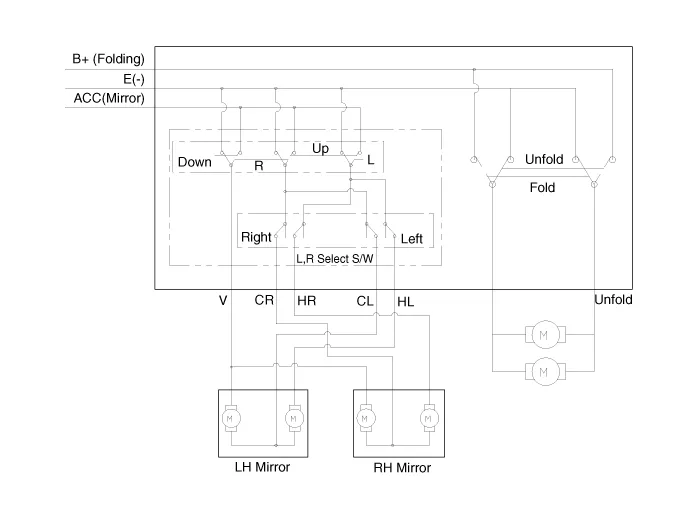
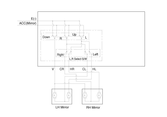
| Circuit Diagram |
| [Folding Mirror Type] |
| [Non-Folding Mirror Type] |
Repair procedures
| Inspection |
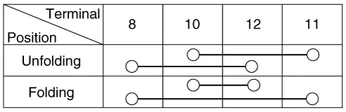
| 1. | Check for continuity between the terminals in each switch position according to the table.
[Power Mirror Switch]
[Power Folding Mirror Switch]
|

| Removal |
|

| 1. | Disconnect the negative (-) battery terminal. |
| 2. | Remove the front left door trim.
(Refer to Body - "Front Door Trim")
|
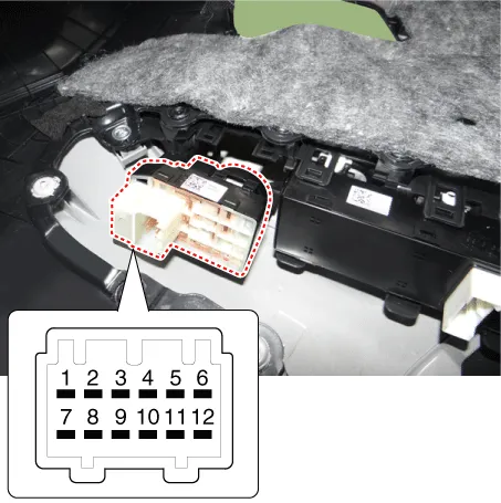
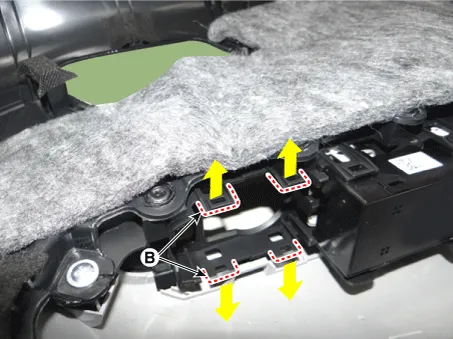
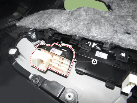
| 3. | Remove the power mirror switch assembly (A) by pulling out both ends of the switch holders (B).
|
| Installation |
| 1. | Install the power mirror switch. |
| 2. | Install the front door trim after connecting the connector. |
| 3. | Connect the negative (-) battery terminal. |
Components and components location Component Location 1. Power door mirror 2. Power door mirror switch 3. Power folding mirror switch
Components and components location Components 1. Side repeater lamp Repair procedures Inspection 1. Disconnect the negative (-) battery terminal.
Other information:
Kia Picanto (JA) 2017-2026 Service & Repair Manual: ESCL(Electronic Steering Column Lock)
Components and components location Component Repair procedures Removal 1.Disconnect the negative(-) battery terminal. 2.Remove the crash pad lower panel. (Refer to Body - "Crash Pad Lower Panel") 3.Remove the steering column upper and lower shrouds.
Kia Picanto (JA) 2017-2026 Service & Repair Manual: Windshield Wiper-Washer Switch
Repair procedures Removal 1.Disconnect the negative (-) battery terminal. 2.Remove the steering column upper and lower shrouds after loosening the screws. (Refer to Body - "Steering Column Shroud Panal") 3.Disconnect the wiper switch / washer switch connector (A).
Categories
- Manuals Home
- Kia Picanto Owners Manual
- Kia Picanto Service Manual
- To set cruise control speed
- Heating,Ventilation, Air Conditioning
- Clutch Cable
- New on site
- Most important about car
