Kia Picanto (JA): Lighting System / License Lamps
Repair procedures
| Removal |
| 1. | Disconnect the negative (-) battery terminal. |
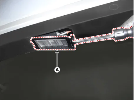
| 2. | Remove the license lamp assembly (A) after pressing the locking pin.
|
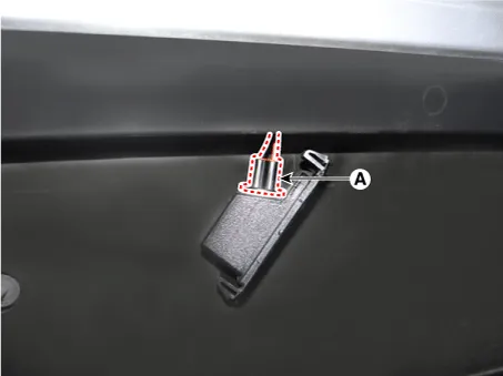
| 3. | Disconnect the license lamp connector (A).
|
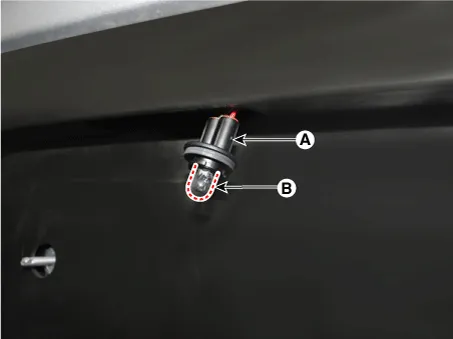
| 4. | Remove the license lamp bulb (B) after removing the license lamp socket (A).
|
| Installation |
| 1. | Install the license lamp bulb. |
| 2. | Connect the license lamp connector. |
| 3. | Install the license lamp assembly. |
| 4. | Connect the negative (-) battery terminal. |
Repair procedures Removal 1.Disconnect the negative (-) battery terminal. 2.Remove the front bumper assembly. (Refer to Body - "Front Bumper Assembly") 3.
Repair procedures Removal 1. Disconnect the negative (-) battery terminal. 2. Open the tailgate. 3. Loosen the high mounted stop lamp mounting nuts (A).
Other information:
Kia Picanto (JA) 2017-2026 Service & Repair Manual: Rear Wiper Motor
Repair procedures Inspection Rear Wiper Motor 1.Remove the connector from the rear wiper motor. 2.Connect positive (+) battery cables to terminal 1 and negative (-) battery cables to terminal 2 respectively. 3.Check that the motor operates normally.
Kia Picanto (JA) 2017-2026 Service & Repair Manual: Smart Key System
Specifications Specifications Smart Key Unit Items Specification Rated voltage DC 12 V Operating voltage DC 9 - 16 V Operating temperature -31 - 167°F (-35 - 75°C) Load Max. 4mA (When welcome light function "OFF") RF Receiver Items
Categories
- Manuals Home
- Kia Picanto Owners Manual
- Kia Picanto Service Manual
- Engine Control / Fuel System
- Engine Mechanical System
- Cylinder Head
- New on site
- Most important about car
