Kia Picanto (JA): Lighting System / Front Fog Lamps
Repair procedures
| Removal |
| 1. | Disconnect the negative (-) battery terminal. |
| 2. | Remove the front bumper assembly.
(Refer to Body - "Front Bumper Assembly")
|
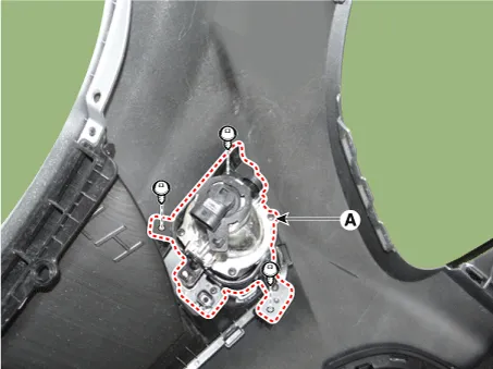
| 3. | Remove the front fog lamp assembly (A) after loosening the mounting screws.
|
| Bulb Replacement |
| 1. | Remove the engine room under cover.
G 1.0 MPI (Refer to Engine Mechanical System - "Engine Room Under Cover")
G 1.2 MPI (Refer to Engine Mechanical System - "Engine Room Under Cover")
|
| 2. | Remove the front fog lamp socket (A) after turning in the counterclockwise direction.
|

| Installation |
| 1. | Install the front fog lamp assembly. |
| 2. | Install the front bumper assembly. |
| 3. | Connect the negative (-) battery terminal. |
Repair procedures Inspection 1.Check for continuity between terminals. If the continuity is not as specified, replace the hazard lamp switch. No.
Repair procedures Removal 1. Disconnect the negative (-) battery terminal. 2. Remove the license lamp assembly (A) after pressing the locking pin.
Other information:
Kia Picanto (JA) 2017-2026 Service & Repair Manual: Indicators And Gauges
Troubleshooting Troubleshooting Error Item Failure symptom Inspection items Detailed inspections Relevant Parts/ Components Screen display LCD scree
Kia Picanto (JA) 2017-2026 Service & Repair Manual: Seat Heater
Components and components location Component Location 1. Seat heater unit 2. Front seat back heater 3. Front seat cushion heater Schematic diagrams Circuit Diagram Repair procedures Inspection 1.Check for continuity and measure the resistance between terminals No 1 and No 4.
Categories
- Manuals Home
- Kia Picanto Owners Manual
- Kia Picanto Service Manual
- Fuel Delivery System
- Body Electrical System
- Engine Oil and Filter
- New on site
- Most important about car
