Kia Picanto (JA): Timing System / Timing Chain Cover & Oil Pump Assembly
Repair procedures
| Removal |
|

Mark all wiring and hoses to avoid misconnection. |

| 1. | Disconnect the negative battery terminal. |
| 2. | Remove the air cleaner assembly.
(Refer to Intake and Exhaust System - "Air Cleaner")
|
| 3. | Remove the RH side front wheel.
(Refer to Suspension System - "Wheel")
|
| 4. | Remove the engine room under cover and RH side cover.
(Refer to Engine and Transaxle Assembly - "Engine Room Under Cover")
|
| 5. | Drain the coolant.
(Refer to Cooling System - "Coolant")
|
| 6. | Remove the drive belt.
(Refer to Drive Belt System - "Drive Belt")
|
| 7. | Remove the alternator.
(Refer to Engine Electrical System - "Alternator")
|
| 8. | Remove the drive belt tensioner
(Refer to Drive Belt System - "Drive Belt Tensioner")
|
| 9. | Remove the water pump.
(Refer to Cooling System - "Water Pump")
|
| 10. | Remove the crankshaft damper pulley.
(Refer to Drive Belt System - "Crankshaft Damper Pulley")
|
| 11. | Remove the crankshaft position sensor (CKPS).
(Refer to Engine Control / Fuel System - "Crankshaft Position Sensor (CKPS)")
|
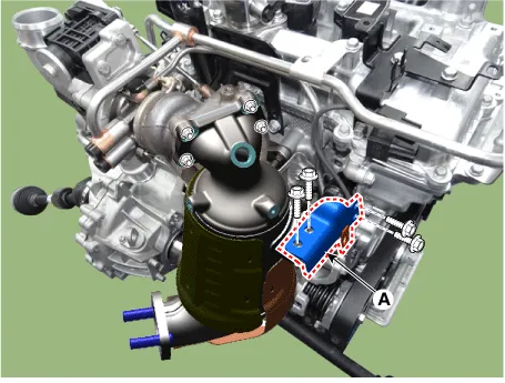
| 12. | Remove the warm-up catalytic converter (WCC) upper stay (A).
|
| 13. | Remove the intake manifold.
(Refer to Intake and Exhaust System - "Intake Manifold")
|
| 14. | Remove the thermostat and heater pipe.
(Refer to Cooling System - "Thermostat")
|
| 15. | Remove the cylinder head cover.
(Refer to Cylinder Head Assembly - "Cylinder Head Cover")
|
| 16. | Install the jack to the edge of upper oil pan to support the engine.
|
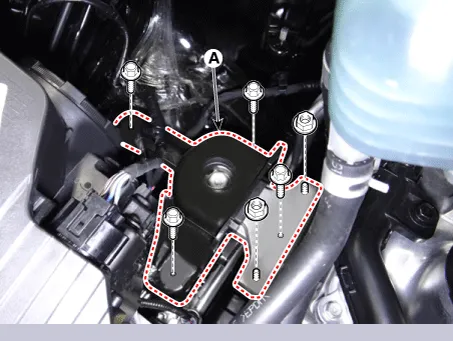
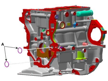
| 17. | Remove the engine mounting support bracket (A).
|
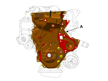
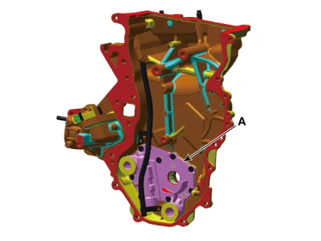
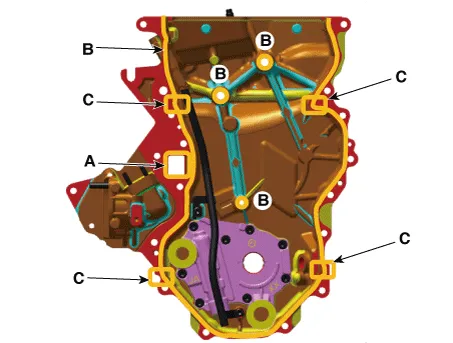
| 18. | Remove the timing chain cover & oil pump assembly (A).
|
| Installation |
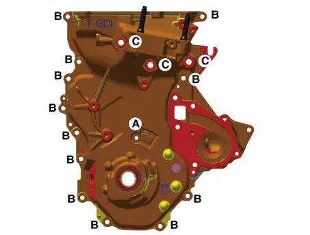
| 1. | Install the timing chain cover & oil pump assembly.
|
| 2. | Install the remaining parts in the reverse order of removal. |
Repair procedures Replacement 1.Remove the crankshaft damper pulley. (Refer to Drive Belt System - "Crankshaft Damper Pulley") 2.
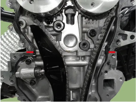
Repair procedures Removal 1.Turn the crankshaft pulley and align its groove with the timing mark of the chain cover & oil pump assembly to set the piston of No.
Other information:
Kia Picanto (JA) 2017-2026 Service & Repair Manual: License Lamps
Repair procedures Removal 1. Disconnect the negative (-) battery terminal. 2. Remove the license lamp assembly (A) after pressing the locking pin. 3. Disconnect the license lamp connector (A). 4. Remove the license lamp bulb (B) after removing the license lamp socket (A).
Kia Picanto (JA) 2017-2026 Service & Repair Manual: Smart Key System
Specifications Specifications Smart Key Unit Items Specification Rated voltage DC 12 V Operating voltage DC 9 - 16 V Operating temperature -31 - 167°F (-35 - 75°C) Load Max. 4mA (When welcome light function "OFF") RF Receiver Items
Categories
- Manuals Home
- Kia Picanto Owners Manual
- Kia Picanto Service Manual
- Body Electrical System
- Coolant
- Charging System
- New on site
- Most important about car
