Kia Picanto (JA): Headlamp Leveling System / Headlamp Leveling Switch
Schematic diagrams
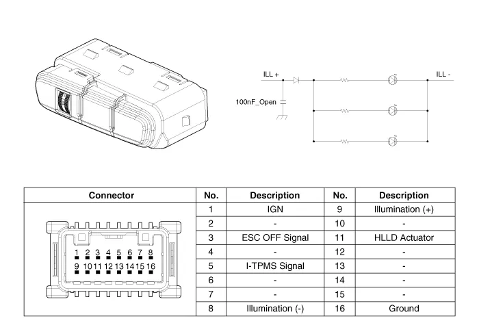
| Circuit Diagram |
Repair procedures
| Removal |
| 1. | Disconnect the negative (-) battery terminal. |
| 2. | Remove the crash pad lower panel.
(Refer to Body - "Crash Pad Lower Panel")
|
| 3. | Remove the crash pad side switch (A) after loosening the mounting screws.
|

| Installation |
| 1. | Install the crash pad side switch. |
| 2. | Install the crash pad lower panel. |
| 3. | Connect the negative (-) battery terminal. |
Components and components location Components Repair procedures Removal 1.Disconnect the negative (-) battery terminal. 2.Remove the headlamp assembly.
Components and components location Component Location 1. Horn switch 2. Horn relay 3. Horn 4. Clock spring Repair procedures Removal 1.
Other information:
Kia Picanto (JA) 2017-2026 Service & Repair Manual: Start/Stop Button
Components and components location Component Repair procedures Removal 1.Disconnect the negative (-) battery terminal. 2.Remove the crash pad lower panel. (Refer to Body - "Crash Pad Lower Panel") 3.Remove the steering column shroud lower panel.
Kia Picanto (JA) 2017-2026 Service & Repair Manual: Immobilizer Control Unit
Repair procedures Removal 1.Disconnect the negative (-) battery terminal. 2.Remove the main crash pad assembly. (Refer to Body - "Main Crash Pad Assembly") 3.Disconnect the connector of the immobilizer unit and then remove the immobilizer unit (A) after loosening a bolt.
Categories
- Manuals Home
- Kia Picanto Owners Manual
- Kia Picanto Service Manual
- Normal Condition
- Suspension System
- Front Disc Brake
- New on site
- Most important about car
