Kia Picanto (JA): Sunroof / Sunroof Motor
Repair procedures
| Inspection |
| 1. | Disconnect the negative (-) battery terminal. |
| 2. | Remove the roof trim assembly.
(Refer to Body - "Roof Trim Assembly")
|
| 3. | Remove the glass motor (A) after loosening the mounting screws.
|
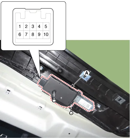
| 4. | Ground the terminals as below table, and check that the sunroof unit operates as below table.
|
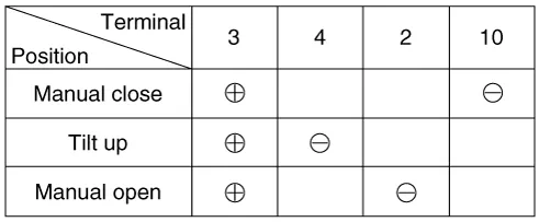
| 5. | Make
these input tests at the connector. If any test indicates a problem,
find and correct the cause, then recheck the system. If all the input
tests prove OK, the sunroof motor must be faulty; replace it.
|
| Adjustment |
| 1. | Turn the ignition key to the ON position. |
| 2. | According to the position of the sunroof, do as follows.
|
| 3. | Release the TILT button. |
| 4. | Press
and hold the TILT button once again until the sunroof has returned to
the original position of TILT after it is raised a little higher than
the maximum TILT position. |
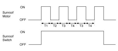
| 1. | The Sunroof ECU detects the Run- time of motor |
| 2. | Motor can be operated continuously for the 1st Run-time. |
| 3. | Motor which is operated continuously stops operating after the 1st Run-time. |
| 4. | And then Motor is not operated for the 1st Cool-time. |
| 5. | Motor is operated for the 2nd Run-time at the continued motor operation after 1st Cool-time. |
| 6. | Motor which is operated continuously stops operating after the 2nd Run-time. |
| 7. | Motor is not operated for the 2nd Cool-time. |
| 8. | Motor repeats the 2nd Run-time and 2nd Cool-time at the continued motor operation.
|
| 1. | The Sunroof ECU detects the Run- time of motor. |
| 2. | Motor can be operated continuously for the 1st Run-time. |
| 3. | Motor which is operated continuously stops operating after the 1st Run-time. |
| 4. | And then Motor is not operated for the 1st Cool-time. |
| 5. | Motor is operated for the 2nd Run-time at the continued motor operation after 1st Cool-time. |
| 6. | Motor which is operated continuously stops operating after the 2nd Run-time. |
| 7. | Motor is not operated for the 2nd Cool-time. |
| 8. | Motor repeats the 2nd Run-time and 2nd Cool-time at the continued motor operation.
T1 : 120 ± 10 sec., T2 : 18 ± 2 sec., T3 : 9 ± 2 sec., T4 : 18 ± 2 sec. |
Components and components location Components Repair procedures Inspection 1. Disconnect the negative (-) battery terminal. 2. Remove the map lamp lens (A).
Components and components location Component Location 1. Windshield wiper arm & blade 2. Wiper & washer switch 3. Windshield washer hose & nozzle 4.
Other information:
Kia Picanto (JA) 2017-2026 Service & Repair Manual: Keyless Entry And Burglar Alarm
Specifications Specification Item Specification Power source 3 V Operating temperature -22 - 167°F (-30 - 75°C) RF Modulation FSK LF Modulation ASK RF frequency 433.92 MHz Button number 3 Function Door lock Door unlock Tailgate unlock Components and components locat
Kia Picanto (JA) 2017-2026 Service & Repair Manual: Map Lamp
Repair procedures Removal • Put on gloves to prevent hand injuries. • When removing with a flat-tip screwdriver or remover, wrap protective tape around the tools to prevent damage to components.
Categories
- Manuals Home
- Kia Picanto Owners Manual
- Kia Picanto Service Manual
- Engine Mechanical System
- Coolant
- Thermostat
- New on site
- Most important about car
