Kia Picanto (JA): Sunroof / Sunroof Switch
Components and components location
| Components |

Repair procedures
| Inspection |
| 1. | Disconnect the negative (-) battery terminal. |
| 2. | Remove the map lamp lens (A). |
| 3. | Remove the map lamp (B) after loosening the mounting screws.
|
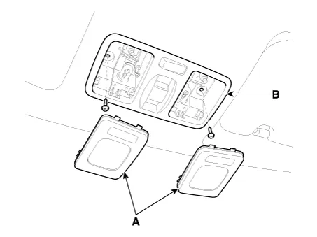
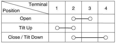
| 4. | Check for continuity between the terminals. If the continuity is not shown as specified, replace the panoramaroof switch.
|

Components and components location Component Location 1. Sunroof 2. Sunroof switch 3. Sunroof motor & controller Schematic diagrams Circuit Diagram
Repair procedures Inspection 1.Disconnect the negative (-) battery terminal. 2.Remove the roof trim assembly. (Refer to Body - "Roof Trim Assembly") 3.
Other information:
Kia Picanto (JA) 2017-2026 Service & Repair Manual: Junction Box (Engine Compartment)
Components and components location Component Location E/R Junction Box Circuit (E/R Junction Block) E/R Junction Box Circuit (E/R Junction Block) Repair procedures Inspection 1. Disconnect the negative (-) battery terminal.
Kia Picanto (JA) 2017-2026 Service & Repair Manual: Blower Unit
Components and components location Component Location 1. Blower Unit Components 1. Intake Actuator 2. Intake Case [Lower] 3. Air Filter 4. FET 5. Resister 6. Intake Seal 7. Intake Case [Upper] 8. Intake Door Assembly 9. Anti Noise Pad 10.
Categories
- Manuals Home
- Kia Picanto Owners Manual
- Kia Picanto Service Manual
- Fuel Delivery System
- Engine Mechanical System
- Engine Oil and Filter
- New on site
- Most important about car
