Kia Picanto (JA): Front Suspension System / Sub Frame
Repair procedures
| Removal |
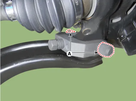
| 1. | Remove the universal joint bolt (A).
|


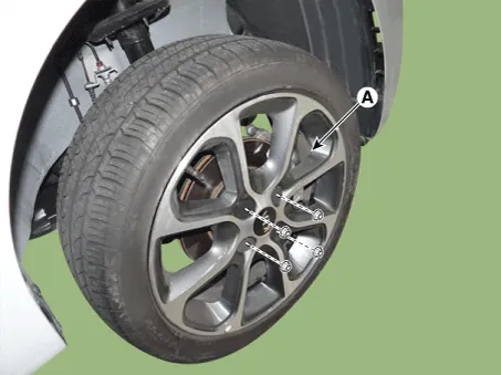
| 2. | Remove the front wheel tire (A).
|
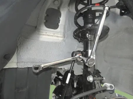
| 3. | Remove the lower arm bolt and nut.
|

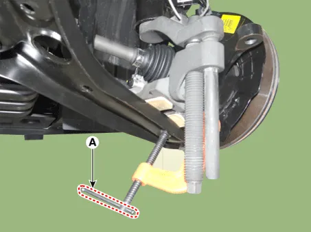
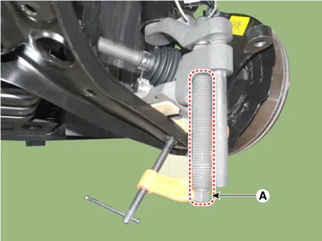
| 4. | Remove the front lower arm from the front knuckle using the SST (0K545-A9100).
|

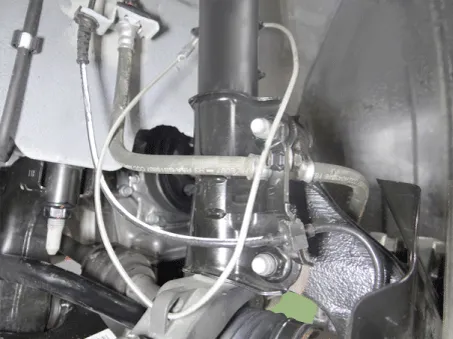

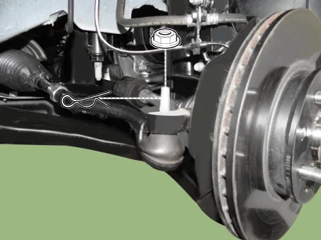
| 5. | Remove the pin and nut from the tie rod end ball joint.
|
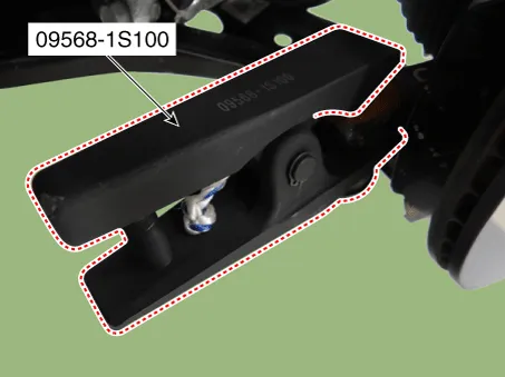
| 6. | Remove the tie rod end ball joint from the knuckle by using the SST (09568-1S100).
|
| 7. | Remove the stabilizer link nut.
|
| 8. | Remove the roll rod bracket.
G 1.0 MPI (Refer to Engine Mechanical System - "Engine Mounting")
G 1.2 MPI (Refer to Engine Mechanical System - "Engine Mounting")
|
| 9. | Remove the muffler hanger.
|

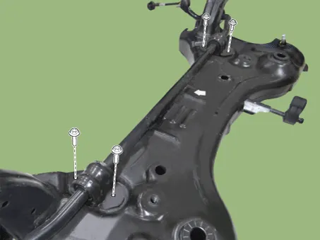
| 10. | Loosen the bolts & nuts and then remove the sub frame (A).
|

| 11. | Remove the gear box heat protector.
|

| 12. | Loosen the gear box mounting bolts and then remove the gear box.
|

| 13. | Loosen the bolts and then remove the stabilizer bar assembly.
|
| 14. | Install in the reverse order of removal. |
| 15. | Check the wheel alignment.
(Refer to Tires/Wheels - "Alignment")
|
Repair procedures Removal 1.Remove the universal joint bolt (A). Tightening torque : 32.4 - 37.3 N·m (3.3 - 3.8 kgf·m, 23.9 - 27.
Components and components location Components [Disc type] 1. Torsion beam 2. Brake disc 3. Brake caliper [Drum type] 1. Torsion beam axle 2.
Other information:
Kia Picanto (JA) 2017-2026 Service & Repair Manual: Rear Combination Lamp
Repair procedures Removal 1.Disconnect the negative (-) battery terminal. 2.Remove the rear combination lamp (A) after loosening the screws. 3.Remove the rear combination lamp packing (A). 4.Disconnect the rear combination lamp connector (A).
Kia Picanto (JA) 2017-2026 Service & Repair Manual: Blower Resistor (Manual)
Repair procedures Inspection 1.Measure terminal - to - terminal resistance of blower resistor. 2.measured resistance is not within specification, the blower resistor must be replaced. (After removing the resistor) Replacement 1.Disconnect the negative (-) battery terminal.
Categories
- Manuals Home
- Kia Picanto Owners Manual
- Kia Picanto Service Manual
- Coolant
- Timing Chain
- To set cruise control speed
- New on site
- Most important about car
