Kia Picanto (JA): Fuses And Relays / Junction Box (Engine Compartment)
Components and components location
| Component Location |
| E/R Junction Box |
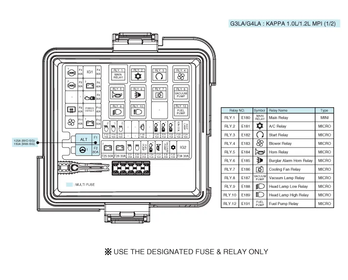
| Circuit (E/R Junction Block) |

| E/R Junction Box |
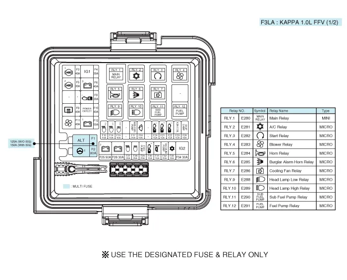
| Circuit (E/R Junction Block) |

Repair procedures
| Inspection |
| 1. | Disconnect the negative (-) battery terminal. |
| 2. | Pull out the relay from the engine compartment relay block. |
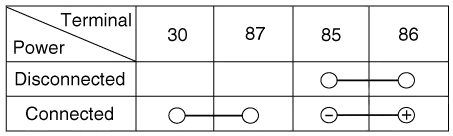
| 1. | After
supplying power to between No. 85 and 86 power relay terminals, check
that there is continuity between No. 30 and 87 terminals. |
| 2. | After
disconnecting power between No. 85 and 86 power relay terminals, check
that there is no continuity between No. 30 and 87 terminals. Engine Room Relay Block
|


| 1. | After
supplying power to between No. 85 and 86 power relay terminals, check
that there is continuity between No. 30 and 87 terminals. |
| 2. | After
disconnecting power between No. 85 and 86 power relay terminals, check
that there is no continuity between No. 30 and 87 terminals.
|


| 1. | Check that the fuse holders are loosely held and that the fuses are securely fixed by the holders. |
| 2. | Check that each fuse circuit has the exact fuse capacity. |
| 3. | Check the fuses for any damage.
|

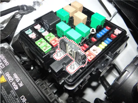
| 1. | Disconnect the negative (-) battery terminal. |
| 2. | Remove the power cable terminals (A) after loosening the nuts from the engine room fuse & relay box.
|

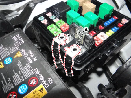
| 3. | Remove the multi fuse (A) after pushing the hook.
|

Components and components location Component Location [Engine Room] 1. Engine room relay block [Interior Relay] 1. Interior junction block
Components and components location Component Location I/P Junction Box Circuit (I/P Junction Box) Description and operation Description Communication Network Diagram Abbreviation Explanation ABS Anti-lock Brake System ACU Airbag Control Unit AEB Autonomous Emergency Braking B-CAN Body Controller Area Network BCM Body Control Module C-CAN Chassis Controller Area Network CLU Cluster Module DATC Dual Automatic Temp Control EMS Engine Management System ESC Electronic Control Suspention EVP Eva Vacuum Pump I-BOX Telematics System LPI Liquid Petroleum Injection H_U Head Unit (Audio / AVN) M-CAN Multi media Controller Area Network MDPS Motor Driven Power Steering PGS Parking Guide System SLM Seat belt remind & Lighting Module SMK Smart Key Unit TCU Transmission Control Unit TMU Telematics System TPMS Tire Pressure Monitoring System Repair procedures Fuse Inspection 1.
Other information:
Kia Picanto (JA) 2017-2026 Service & Repair Manual: Button Engine Start System
Components and components location Component Location 1. Body control module (BCM) 2. Smart key unit (SMK) 3. Interior antenna 1 4. Interior antenna 2 5. FOB key 6. Start Stop Button (SSB) 7. Door handle & door antenna 8. Bumper antenna 9.
Kia Picanto (JA) 2017-2026 Service & Repair Manual: Power Door Locks
Components and components location Component Location 1. Driver power window switch 2. Assist power window switch 3 . Body Comtrol Module (BCM) 4 . Door lock knob 5 . Tailgate actuator 6. Door latch lock actuator 7 . Door lock/unlock switch 8 .
Categories
- Manuals Home
- Kia Picanto Owners Manual
- Kia Picanto Service Manual
- Engine Oil and Filter
- Coolant
- Battery
- New on site
- Most important about car
