Kia Picanto (JA): Front Suspension System / Front Stabilizer Bar
Repair procedures
| Removal |
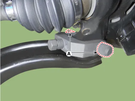
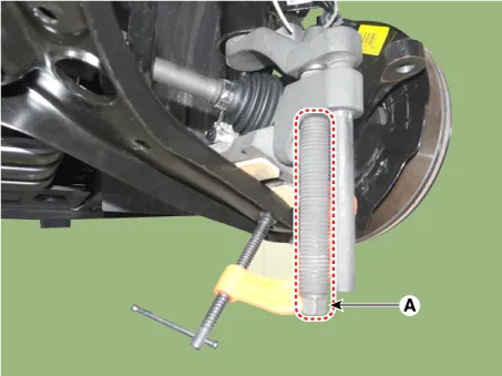
| 1. | Remove the universal joint bolt (A).
|


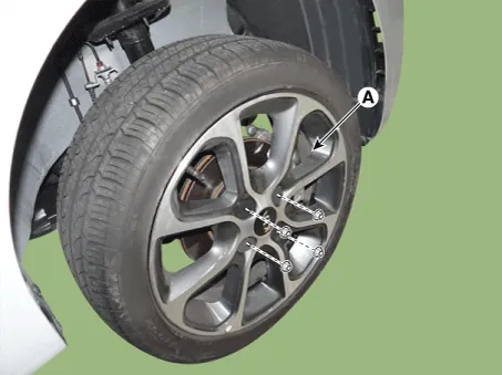
| 2. | Remove the front wheel tire (A).
|
| 3. | Remove the lower arm bolt and nut.
|

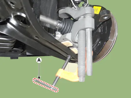
| 4. | Remove the front lower arm from the front knuckle using the SST (0K545-A9100).
|


| 5. | Remove the pin and nut from the tie rod end ball joint.
|
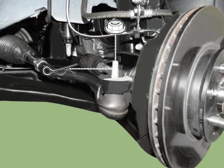
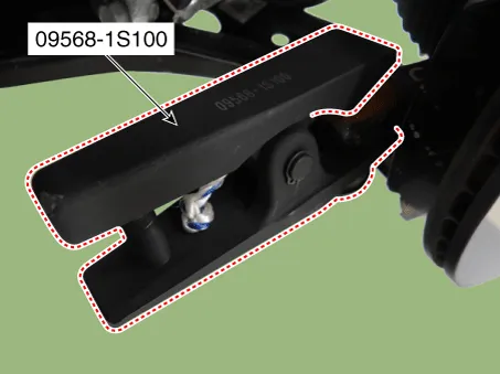
| 6. | Remove the tie rod end ball joint from the knuckle by using the SST (09568-1S100).
|
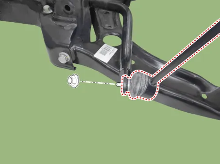
| 7. | Remove the stabilizer link nut.
|
| 8. | Remove the roll rod bracket.
G 1.0 MPI (Refer to Engine Mechanical System - "Engine Mounting")
G 1.2 MPI (Refer to Engine Mechanical System - "Engine Mounting")
|
| 9. | Remove the muffler hanger.
|

| 10. | Loosen the bolts & nuts and then remove the sub frame (A).
|

| 11. | Remove the gear box heat protector.
|

| 12. | Loosen the gear box mounting bolts and then remove the gear box.
|

| 13. | Loosen the bolts and then remove the stabilizer bar assembly.
|
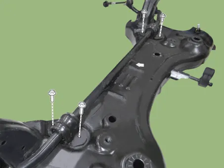
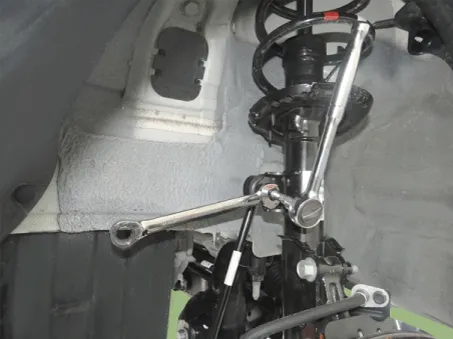
| 14. | Loosen the nut and then remove the stabilizer link.
|
| 15. | Install in the reverse order of removal. |
| 16. | Check the wheel alignment.
(Refer to Tires/Wheels - "Alignment")
|
| Inspection |
| 1. | Check the bushing for wear and deterioration. |
| 2. | Check the front stabilizer bar for deformation. |
| 3. | Check the front stabilizer link ball joint for damage. |
Repair procedures Removal 1.Remove the front/rear wheel tire (A). Tightening torque: 107.9 - 127.5 N·m (11.0 - 13.0 kgf·m, 79.
Repair procedures Removal 1.Remove the universal joint bolt (A). Tightening torque : 32.4 - 37.3 N·m (3.3 - 3.8 kgf·m, 23.9 - 27.
Other information:
Kia Picanto (JA) 2017-2026 Service & Repair Manual: Back View Camera System
Components and components location Component Location 1. Back view camera 2. AVN head unit 3. steering angle sensor Description and operation Description 1. To display back of the vehicle to assist the driver, it receives vehicle rearside image signal from the rearview camera and displays it on AVN head unit monitor
Kia Picanto (JA) 2017-2026 Service & Repair Manual: Heater & A/C Control Unit(Manual)
Components and components location Components [NON ISG] Connector pin function No. Connector A Connector B 1 Low Battery 2 Common Illumination (+) 3 Ground HTD 4 Middle (Low) ISG Battery 5 Middle (High) - 6 High Detent out (-) 7 - 8 Sen
Categories
- Manuals Home
- Kia Picanto Owners Manual
- Kia Picanto Service Manual
- Normal Condition
- Coolant
- Engine Mechanical System
- New on site
- Most important about car
