Kia Picanto (JA): Clutch System / Clutch Cable
Components and components location
| Components |

| 1. Clutch pedal assembly | 2. Clutch cable |
Repair procedures
| Removal |
| 1. | Turn ignition switch OFF and disconnect the negative (-) battery cable. |
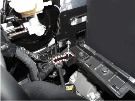
| 2. | Loosen the clutch cable adjust nut (A) and then separate the clutch cable
|

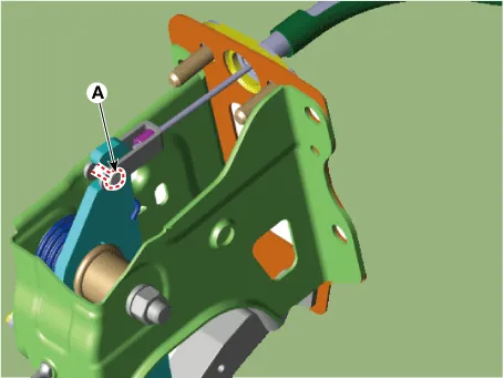
| 3. | Loosen the bolts (A) and then remove the clutch cable bracket.
|

| 4. | Loosen the bolt and then remove the clutch cable bracket from the battery tray.
|
| 5. | Remove the clutch cable bracket by using the driver.
|

| 6. | Remove the battery.
G 1.0 MPI KAPPA (Refer to Engine Electrical System - "Battery")
G 1.2 MPI KAPPA (Refer to Engine Electrical System - "Battery")
F 1.0 KAPPA FFV (Refer to Engine Electrical System - "Battery")
|
| 7. | Remove the ECM.
G 1.0 MPI KAPPA (Refer to Engine Control / Fuel System - Engine Control Module (ECM)")
G 1.2 MPI KAPPA (Refer to Engine Control / Fuel System - Engine Control Module (ECM)")
F 1.0 KAPPA FFV (Refer to Engine Control / Fuel System - Engine Control Module (ECM)")
|
| 8. | Loosen the clutch cable bracket nut.
|

| 9. | Remove the crash pad lower panel.
(Refer to Body - "Crash Pad Lower Panel")
|
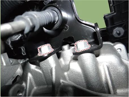
| 10. | Pushing the clutch pedal and then remove the clutch cable (A).
|

| 11. | Loosen the nuts (A) and then remove the clutch pedal.
|

| Installation |
| 1. | Tighten the clutch cable bracket nut.
|
| 2. | Tighten the nuts (A) and then install the clutch cable and clutch pedal bracket.
|
| 3. | Install the clutch cable (A).
|

| 4. | Insert the cable damper to the clutch bracket hole.
|
| 5. | Install the clutch cable bracket.
|
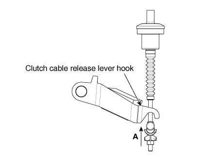
| 6. | Install the cable end to the clutch release lever hook.
|
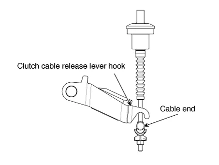
| 7. | Attach cable end to clutch release lever hook, by lifting clutch pedal in (A) direction.
|
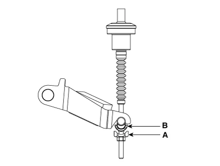
| 8. | Tighten the adjust nut (A) up to (B) position.
|

| 9. | operate the clutch pedal up to full stroke several time.
|

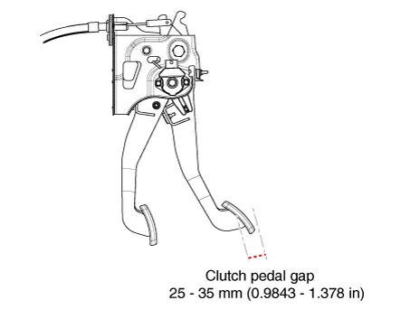
| 10. | Adjust the clutch pedal standard gap value.
|
| 11. | Install the crash pad lower panel.
(Refer to Body - "Crash Pad Lower Panel")
|
| 12. | Install the ECM.
G 1.0 MPI KAPPA (Refer to Engine Control / Fuel System - Engine Control Module (ECM)")
G 1.2 MPI KAPPA (Refer to Engine Control / Fuel System - Engine Control Module (ECM)")
F 1.0 KAPPA FFV (Refer to Engine Control / Fuel System - Engine Control Module (ECM)")
|
| 13. | Install the battery.
G 1.0 MPI KAPPA (Refer to Engine Electrical System - "Battery")
G 1.2 MPI KAPPA (Refer to Engine Electrical System - "Battery")
F 1.0 KAPPA FFV (Refer to Engine Electrical System - "Battery")
|
| Adjustment |
| 1. | Tighten the adjust nut (A) up to (B) position.
|
| 2. | Operate the clutch pedal up to full stroke several time.
|
| 3. | Adjust the clutch pedal standard gap value.
|
Components and components location Components [Kappa 1.0 MPI / FFV, Kappa 1.2 MPI] 1. Clutch pedal assembly 2. Clutch cable [Kappa 1.0 T-GDI] 1.
Components and components location Components [Kappa 1.0 T-GDI] 1. Clutch pedal assembly 2. Ignition lock and clutch switch 3. Master cylinder 4.
Other information:
Kia Picanto (JA) 2017-2026 Service & Repair Manual: Button Engine Start System
Components and components location Component Location 1. Body control module (BCM) 2. Smart key unit (SMK) 3. Interior antenna 1 4. Interior antenna 2 5. FOB key 6. Start Stop Button (SSB) 7. Door handle & door antenna 8. Bumper antenna 9.
Kia Picanto (JA) 2017-2026 Service & Repair Manual: Power Windows
Components and components location Component Location 1. Driver power window switch 2. Assist power window switch 3. Rear power window switch 4. Front window motor 5. Rear window motor Description and operation Safety Function of Power Window When driver door power window auto-up switch is operated, safety function is acti
Categories
- Manuals Home
- Kia Picanto Owners Manual
- Kia Picanto Service Manual
- Suspension System
- Engine Control / Fuel System
- Engine Oil and Filter
- New on site
- Most important about car
