Kia Picanto (JA): Lighting System / Map Lamp
Repair procedures
| Removal |
|

| 1. | Disconnect the negative (-) battery terminal. |
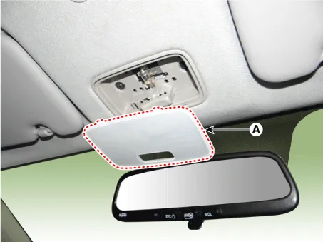
| 2. | Using a screwdriver or remover, separate the map lamp lens (A) from the map lamp.
|
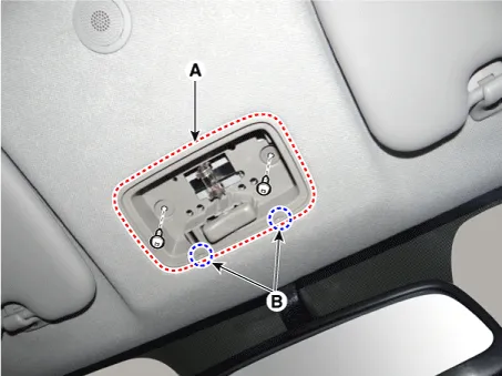
| 3. | Remove the map lamp (A) after loosening the screws.
|

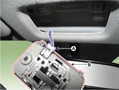
| 4. | Remove the map lamp assembly (B) after disconnecting the map lamp connector (A).
|
| 1. | Using a screwdriver or remover, separate the map lamp lens (A) from the map lamp.
|
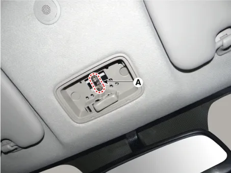
| 2. | Disconnect the map lamp bulb (A).
|
| Installation |
| 1. | Connect the map lamp connector. |
| 2. | Install the map lamp. |
| 3. | Install the map lamp lens. |
| 4. | Connect the negative (-) battery terminal. |
Repair procedures Removal Door Mirror Turn Signal Lamp 1. Disconnect the negative (-) battery terminal. 2. Remove the mirror (A) from the mirror holder.
Repair procedures Inspection 1.Check for continuity between terminals. If the continuity is not as specified, replace the hazard lamp switch. No.
Other information:
Kia Picanto (JA) 2017-2026 Service & Repair Manual: Immobilizer Control Unit
Repair procedures Removal 1.Disconnect the negative (-) battery terminal. 2.Remove the main crash pad assembly. (Refer to Body - "Main Crash Pad Assembly") 3.Disconnect the connector of the immobilizer unit and then remove the immobilizer unit (A) after loosening a bolt.
Kia Picanto (JA) 2017-2026 Service & Repair Manual: Sunroof Switch
Components and components location Components Repair procedures Inspection 1. Disconnect the negative (-) battery terminal. 2. Remove the map lamp lens (A). 3. Remove the map lamp (B) after loosening the mounting screws. 4.
Categories
- Manuals Home
- Kia Picanto Owners Manual
- Kia Picanto Service Manual
- Thermostat
- Engine Mechanical System
- Normal Condition
- New on site
- Most important about car
