Kia Picanto (JA): Immobilizer System / Immobilizer Control Unit
Repair procedures
| Removal |
| 1. | Disconnect the negative (-) battery terminal. |
| 2. | Remove the main crash pad assembly.
(Refer to Body - "Main Crash Pad Assembly")
|
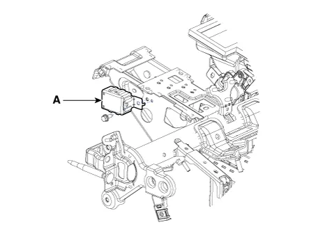
| 3. | Disconnect the connector of the immobilizer unit and then remove the immobilizer unit (A) after loosening a bolt.
|
| Installation |
| 1. | Install the immobilizer control unit after connecting the unit connector. |
| 2. | Install the main crash pad assembly. |
| 3. | Connect the negative (-) battery terminal. |
Schematic diagrams Circuit Diaram Description and operation Description The immobilizer system will disable the vehicle unless the proper ignition key is used, in addition to the currently available anti-theft systems such as car alarms, the immobilizer system aims to drastically reduce the rate of auto theft.
Repair procedures Removal 1.Disconnect the negative (-) battery terminal. 2.Remove the crash pad lower panel. (Refer to Body - "Crash Pad Lower Panel") 3.
Other information:
Kia Picanto (JA) 2017-2026 Service & Repair Manual: Headlamps
Description and operation Description BI-FUNCTION 1. Definition – A headlamp with integrated functions of high and low beam – The light is controlled by rotating the shield inserted to the lens.
Kia Picanto (JA) 2017-2026 Service & Repair Manual: Heater Core
Repair procedures Replacement 1.Disconnect the negative (-) battery terminal. 2.Remove the heater unit. (Refer to Heater - "Heater Unit") 3.Remove the heater core cover (A) after loosening the mounting screws. 4.Pull out the heater core (A) from the heater unit.
Categories
- Manuals Home
- Kia Picanto Owners Manual
- Kia Picanto Service Manual
- Front Disc Brake
- Coolant
- Normal Condition
- New on site
- Most important about car
