Kia Picanto (JA): Lighting System / Hazard Lamp Switch
Repair procedures
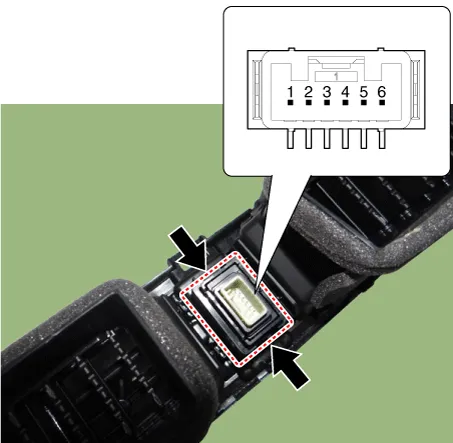
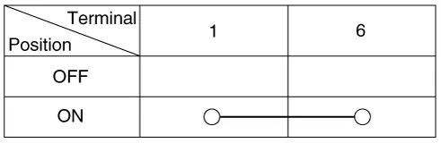
| Inspection |
| 1. | Check for continuity between terminals. If the continuity is not as specified, replace the hazard lamp switch.
|
| Removal |
|

| 1. | Disconnect the negative (-) battery terminal |
| 2. | Remove the center fascia panal.
(Refer to Body - "Center Fascia Panel")
|
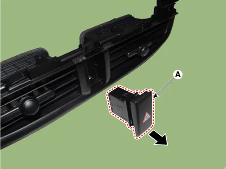
| 3. | Remove the hazard lamp switch (A) by pushing both ends of the switch hooks.
|

| Installation |
| 1. | Install the hazard lamp switch. |
| 2. | Install the center fascia panal. |
| 3. | Connect the negative (-) battery terminal. |
Repair procedures Removal • Put on gloves to prevent hand injuries. • When removing with a flat-tip screwdriver or remover, wrap protective tape around the tools to prevent damage to components.
Repair procedures Removal 1.Disconnect the negative (-) battery terminal. 2.Remove the front bumper assembly. (Refer to Body - "Front Bumper Assembly") 3.
Other information:
Kia Picanto (JA) 2017-2026 Service & Repair Manual: Heater Unit
Components and components location Component Location 1. Heater Unit Components [LH] 1. Heater Core Cover 2. Mode Control Actuator 3. Mode Control Actuator braket 4. Mode Cam 5. Mode Cam 6. Heater Core 7. Door Cover [Floor] 8. Heater Case [LH] [RH] 1.
Kia Picanto (JA) 2017-2026 Service & Repair Manual: Blower Unit
Components and components location Component Location 1. Blower Unit Components 1. Intake Actuator 2. Intake Case [Lower] 3. Air Filter 4. FET 5. Resister 6. Intake Seal 7. Intake Case [Upper] 8. Intake Door Assembly 9. Anti Noise Pad 10.
Categories
- Manuals Home
- Kia Picanto Owners Manual
- Kia Picanto Service Manual
- Brake System
- Automatic Transaxle Fluid
- Engine Control / Fuel System
- New on site
- Most important about car
