Kia Picanto (JA): Brake System / Front Disc Brake
Components and components location
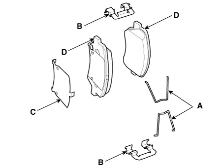
| Components |
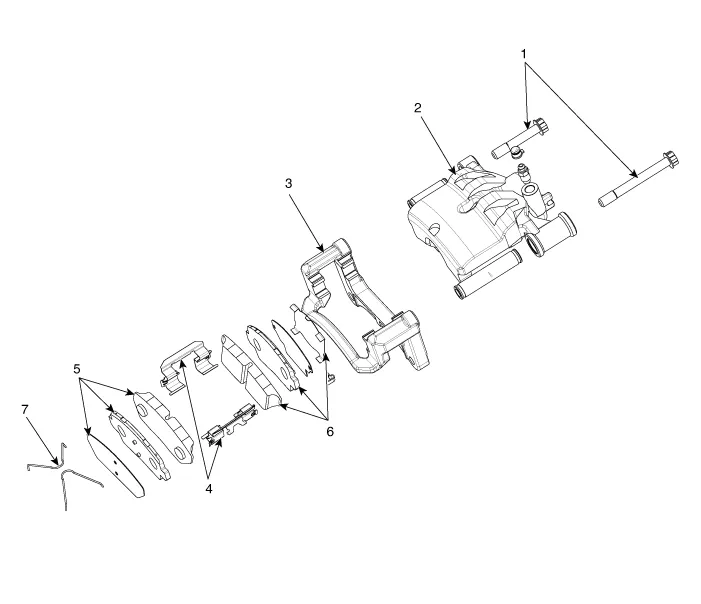
| 1. Guid bolt 2. Caliper body 3. Caliper member 4. Pad liner | 5. Brake pad assembly [OUT] 6. Brake pad assembly [IN] 7. Return spring |
Repair procedures
| Removal |
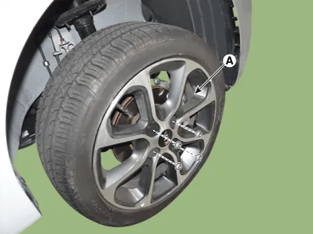
| 1. | Remove the wheel tire (A).
|
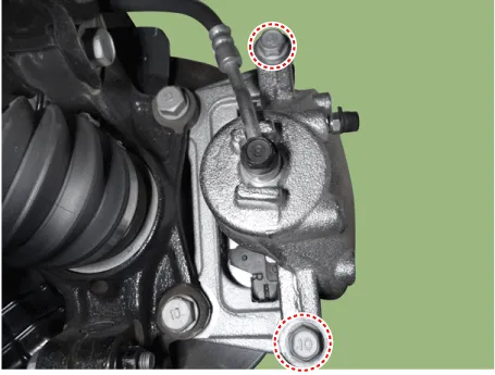
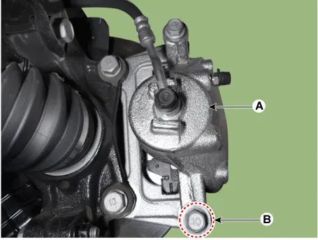
| 2. | Loosen the front brake caliper bolts.
|
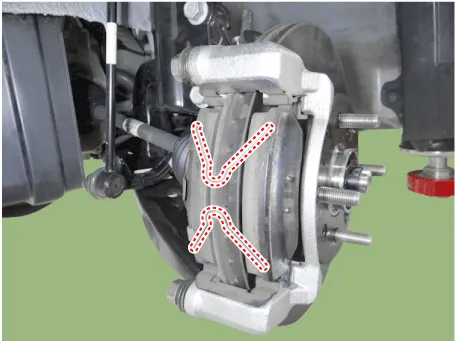
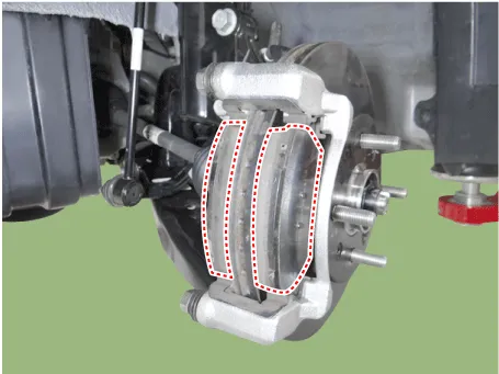
| 3. | Remove the pad return spring and then separate the brake pad.
|
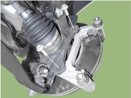
| 4. | Loosen the caliper bolts and then remove the caliper member.
|
| 5. | Loosen the screw and then remove the front brake disc.
|

| Replacement |
| 1. | Remove the wheel tire (A).
|
| 2. | Loosen the guide rod bolt (B) and then pivot the caliper body (A) up out of the way.
|
| 3. | Remove the pad return spring and then separate the brake pad.
|

| Inspection |
| 1. | Check the brake pads for wear and fade. |
| 2. | Check the brake disc for damage and cracks. |
| 3. | Remove
all rust and contamination from the surface, and measure the disc
thickness at 8 points, at least, at the same distance (5mm) apart from
the brake disc outer circle.
|

| 4. | If wear exceeds the limit, replace the discs and pad assembly left and right of the vehicle. |
| 1. | Check the pad wear. Measure the pad thickness and replace it, if it is less than the specified value.
|
| 2. | Check that grease is applied to sliding contact points and check the pad and backing metal for damage.
|

| 1. | Place a dial gauge about 5mm (0.2 in.) from the outer circumference of the brake disc, and measure the runout of the disc.
|
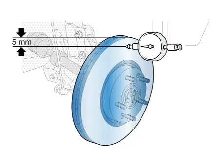
| 2. | If the runout of the brake disc exceeds the limit specification, replace the disc, and then measure the runout again. |
| 3. | If
the runout does not exceed the limit specification, install the brake
disc after turning it 180° and then check the brake disc again for
runout. |
| 4. | If the runout cannot be corrected by changing the position of the brake disc, replace the brake disc. |
| Installation |
| 1. | Install in the reverse order of removal. |
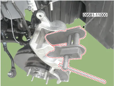
| 2. | Use the SST (09581-11000) when installing the brake caliper assembly.
|
| 3. | After installation, bleed the brake system.
(Refer to Brake system - "Brake System")
|
Components and components location Components 1. Brake member assembly 2. Stop lamp switch 3. Brake Pedal Arm Assembly 4. Brake pedal Pad Repair procedures Removal 1.
Components and components location Components 1. Return spring 2. Brake pad assembly [OUT] 3. Brake pad assembly [IN] 4. Pad liner 5. Brake member 6.
Other information:
Kia Picanto (JA) 2017-2026 Service & Repair Manual: Horn
Components and components location Component Location 1. Horn switch 2. Horn relay 3. Horn 4. Clock spring Repair procedures Removal 1.Disconnect the negative (-) battery terminal. 2.Remove the engine room under cover. G 1.
Kia Picanto (JA) 2017-2026 Service & Repair Manual: Power Door Lock Switch
Repair procedures Inspection 1.Check for continuity between the terminals. If there is an abnormality, replace the switch. Removal • When removing with a flat-tip screwdriver or remover, wrap protective tape around the tools to prevent damage to components.
Categories
- Manuals Home
- Kia Picanto Owners Manual
- Kia Picanto Service Manual
- Body Electrical System
- Engine Mechanical System
- Suspension System
- New on site
- Most important about car
