Kia Picanto (JA): Fuses And Relays / Junction Box (Passenger Compartment)
Components and components location
| Component Location |
| I/P Junction Box |
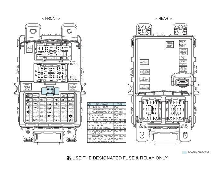
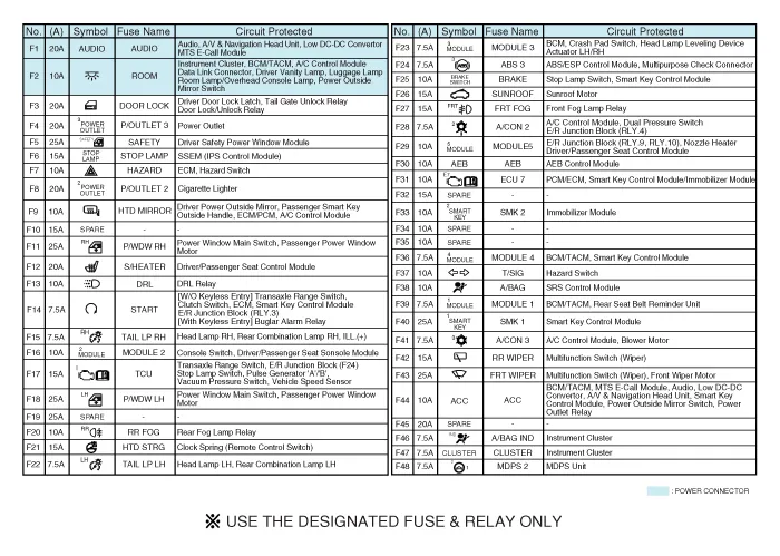
| Circuit (I/P Junction Box) |
Description and operation
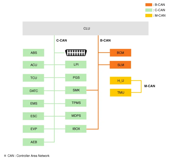
| Description |
|
Abbreviation
|
Explanation
|
| ABS | Anti-lock Brake System |
| ACU | Airbag Control Unit |
| AEB | Autonomous Emergency Braking |
| B-CAN | Body Controller Area Network |
| BCM | Body Control Module |
| C-CAN | Chassis Controller Area Network |
| CLU | Cluster Module |
| DATC | Dual Automatic Temp Control |
| EMS | Engine Management System |
| ESC | Electronic Control Suspention |
| EVP | Eva Vacuum Pump |
| I-BOX | Telematics System |
| LPI | Liquid Petroleum Injection |
| H_U | Head Unit (Audio / AVN) |
| M-CAN | Multi media Controller Area Network |
| MDPS | Motor Driven Power Steering |
| PGS | Parking Guide System |
| SLM | Seat belt remind & Lighting Module |
| SMK | Smart Key Unit |
| TCU | Transmission Control Unit |
| TMU | Telematics System |
| TPMS | Tire Pressure Monitoring System |
Repair procedures
| Fuse Inspection |
| 1. | Check that the fuse holders are loosely held and that the fuses are securely fixed by the holders. |
| 2. | Check that each fuse circuit has the exact fuse capacity. |
| 3. | Check the fuses for any damage.
|

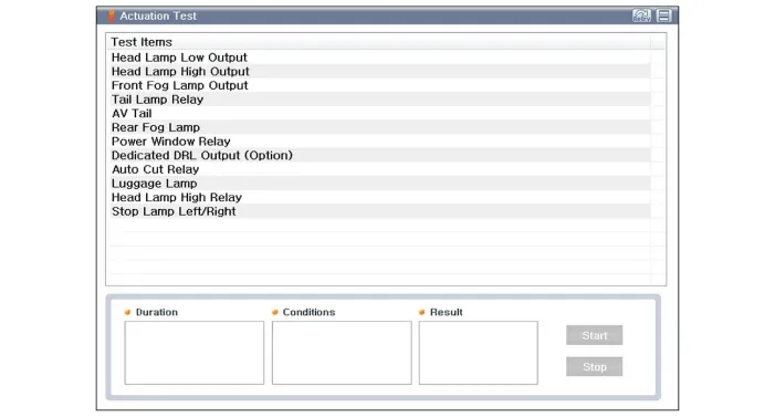
| Diagnosis with KDS/GDS |
| 1. | The
Interior Junction Block can be diagnosed by using the KDS/GDS. The
Interior Junction Block communicates with the KDS/GDS which then
displays inputs and outputs along with codes. |
| 2. | To diagnose the Interior Junction Block function, select the vehicle model, Interior. |
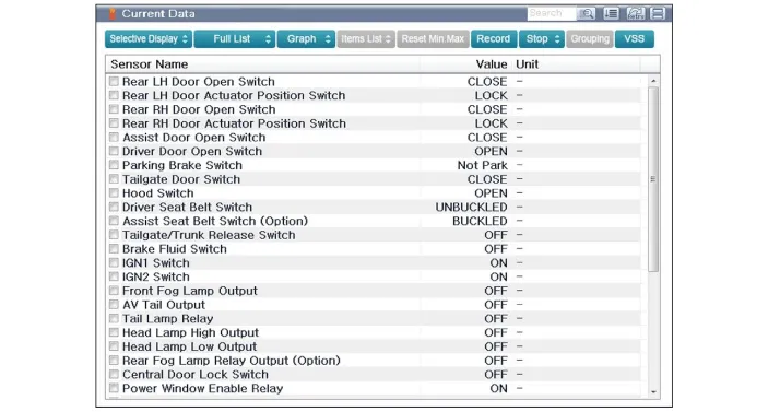
| 3. | To
consult the present input/out value of Interior Junction Block,
"Current DATA". It provides information of Interior Junction Block
input/output conditions.
|
| 4. | To perform functional test on Interior Junction Block outputs, select "Actuation Test"
|
| Removal |
| 1. | Disconnect the negative (-) battery terminal. |
| 2. | Remove the crash pad lower panel.
(Refer to Body - "Crash Pad Lower Panel")
|
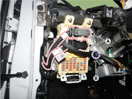
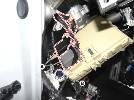
| 3. | Disconnect the connectors (A) from the fuse side of the interior junction block. |
| 4. | Remove the interior junction block wiring mounting clip (B).
|
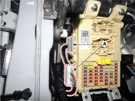
| 5. | Remove the interior junction block side connectors (A).
|
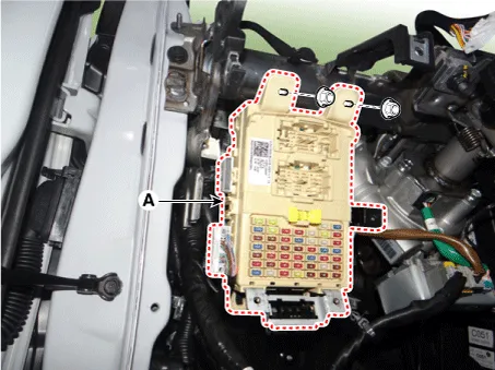
| 6. | Remove the interior junction block (A) after loosening the mounting nuts.
|
| 7. | Disconnect the connectors (A) from the back of the interior junction block. |
| 8. | Remove the interior junction block wiring mounting clip (B).
|
| Installation |
| 1. | Install the interior junction block. |
| 2. | Connect the interior junction block connectors. |
| 3. | Install the crash pad lower panel. |
| 4. | Connect the negative (-) battery terminal. |
| 5. | Check that all systems operate properly. |
Components and components location Component Location E/R Junction Box Circuit (E/R Junction Block) E/R Junction Box Circuit (E/R Junction Block) Repair procedures Inspection 1.
Components and components location Component Location 1. Headlamp leveling actuator 2. Headlamp leveling switch ※ headlamp leveling actuator is built into the headlamp.
Other information:
Kia Picanto (JA) 2017-2026 Service & Repair Manual: Mic
Repair procedures Inspection 1.Disconnect the negative (-) battery terminal. 2.Remove the roof trim assembly. (Refer to Body - "Roof Trim Assembly") 3.Remove the hands free mic (A) after loosening the mounting screws. 4.Check tshe continuity of between terminals.
Kia Picanto (JA) 2017-2026 Service & Repair Manual: Smart Key
Repair procedures Smart Key Smart Key Code Saving 1. Connect the DLC cable of KDS/GDS to the data link connector (16 pins) in driver side crash pad lower panel, turn the power on KDS/GDS. 2. Select the vehicle model and then do "Smart key code saving".
Categories
- Manuals Home
- Kia Picanto Owners Manual
- Kia Picanto Service Manual
- Clutch Cable
- Front Disc Brake
- To set cruise control speed
- New on site
- Most important about car
