Kia Picanto (JA): Lighting System / Headlamps
Description and operation
| Description |
| 1. | Definition
|


| 2. | Structure and mechanism
|


Repair procedures
| Headlamp Aiming Instructions |
| [Mechanical aiming] |
If
there are any regulations pertinent to the aiming of headlamps in the
area where the vehicle is to be used, adjust so as to meet those
requirements. |

| 1. | Inflate the tires to the specified pressure and remove any loads from the vehicle except the driver, spare tire, and tools. |
| 2. | The vehicle should be placed on a flat floor. |
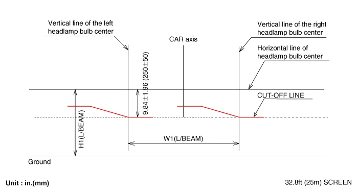
| 3. | Draw
vertical lines (passing through respective headlamp centers) and a
horizontal line (passing through center of headlamps) on the screen. |
| 4. | With
the headlamps and battery in normal condition, aim the headlamps so the
brightest portion falls on the horizontal and vertical lines. A : Vertical B : Horizontal (1) Headlamp (Non-HLLD Type)
(2) Headlamp (HLLD Type)
|


| 1. | Headlamp (Low beam)
[LHD]
[RHD]
|

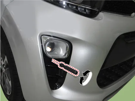
| 2. | Turn the front fog lamp on without the driver aboard. The cut-off line should be projected in the allowable range (shaded region)
|


| Removal |
Headlamps become very hot during use; do not touch them or attach any hardware immediately after turning them off. |

|
| 1. | Disconnect the negative (-) battery terminal. |
| 2. | Remove the front bumper assembly.
(Refer to Body - "Front Bumper Assembly")
|
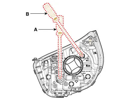
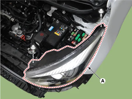
| 3. | Remove the headlamp (A) after loosening the bolts.
|

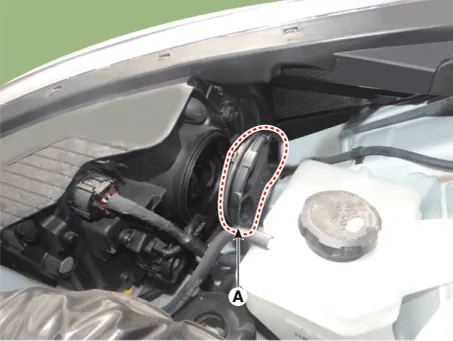
| 4. | Disconnect the headlamp connectors (A).
|

| Installation |
| 1. | Install the headlamp assembly. |
| 2. | Install the front bumper assembly. |
| 3. | Connect the negative (-) battery terminal. |
| Replacement |
| [LH] |
| 1. | Disconnect the negative (-) battery terminal. |
| 2. | Remove the headlamp assembly. |
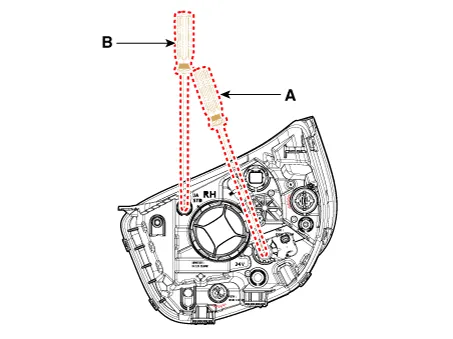
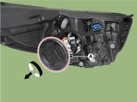
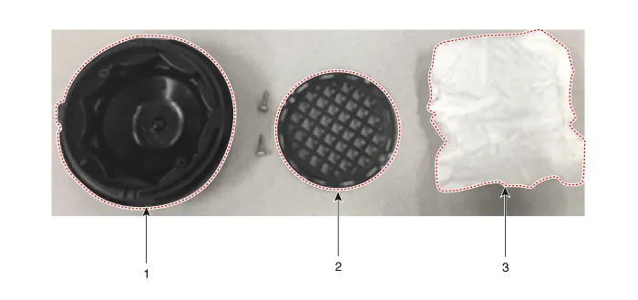
| 3. | Remove the dust caps (A) from the headlamp assembly after turning in the counterclockwise direction.
|
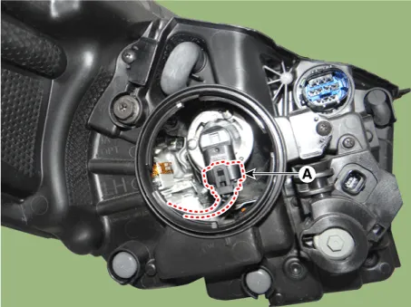
| 4. | Disconnect the headlamp high/low beam bulb connector (A).
|
| 5. | Remove the headlamp high/low beam bulb (A) from the headlamp assembly after turning in the counterclockwise direction.
|

| 6. | Install in the reverse order of removal. |
| [RH] |
| 1. | Turn the headlamp switch off. |
| 2. | Remove the dust caps (A) from the headlamp assembly after turning in the counterclockwise direction.
|
| 3. | Disconnect the headlamp high/low beam bulb connector (A).
|
| 4. | Remove the headlamp high/low beam bulb (A) from the headlamp assembly after turning in the counterclockwise direction.
|
| 5. | Install in the reverse order of removal. |
| 1. | Turn the headlamp switch off. |
| 2. | Remove the bulb socket (A) and bulb (B) from the headlamp assembly.
|

| 3. | Install in the reverse order of removal. |
Components
|

| [LH] |
| 1. | Turn the headlamp switch off. |
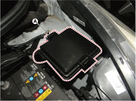
| 2. | Remove the engine room fuse & relay block cover (A).
|
| 3. | Remove the dust caps (A) from the headlamp assembly after turning in the counterclockwise direction.
|

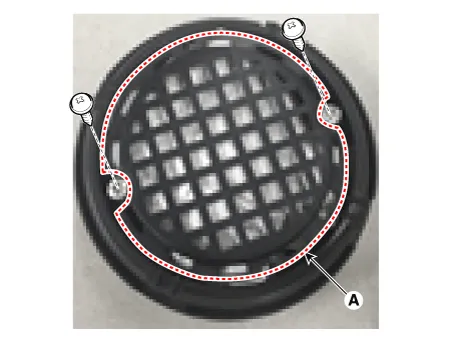
| 4. | Remove the moisture absorbent brakcet (A) from the dust cover after loosening the mounting screws. And then replace the moisture absorbent.
|
| 5. | Install in the reverse order of removal. |
| [RH] |
| 1. | Turn the headlamp switch off. |
| 2. | Remove the dust caps (A) from the headlamp assembly after turning in the counterclockwise direction.
|
| 3. | Remove the moisture absorbent brakcet (A) from the dust cover after loosening the mounting screws. And then replace the moisture absorbent.
|
| 4. | Install in the reverse order of removal. |
Specifications Specification Item Type Bulb Watt (W) Front Headlamp Halogen (Position lamp) Low/High H4 LL 55/60 Turn signal lamp PY21WLL 21 Position lamp W5WLL 5 Halogen (Position lamp + DRL) Low/High HB3 (9005HL+) 60 Turn signal lamp LED LED Position lamp LED LED Daytime Running Light (DRL) LED LED Front fog lamp HB4 51 Turn signal lamp (Side) WY5W 5 Door mirror turn signal lamp LED LED Rear Rear combination lamp Bulb Type Tail lamp W5WLL 5 Tail / Stop lamp P21/5WLL 21 Turn signal lamp PY21WLL 21 Back up lamp W16W 16 LED Type Tail lamp LED LED Tail / Stop lamp LED LED Turn signal lamp PY21WLL 21 Back up lamp W16W 16 High mounted stop lamp Bulb Type W5WLL 5 License plate lamp W5WLL 5 Interior Map lamp W10W 10 Room lamp FESTOON 8 Luggage lamp FESTOON 8 Glove box lamp W5W 10 Components and components location Component Location 1 .
Repair procedures Removal Door Mirror Turn Signal Lamp 1. Disconnect the negative (-) battery terminal. 2. Remove the mirror (A) from the mirror holder.
Other information:
Kia Picanto (JA) 2017-2026 Service & Repair Manual: AVN Antenna
Components and components location Components [Roof Antenna (Radio+GPS/GNSS+DAB+GSM)] Repair procedures Removal Roof antenna 1.Disconnect the negative (-) battery terminal. 2.Remove the roof trim assembly. (Refer to Body - "Roof Trim Assembly") 3.
Kia Picanto (JA) 2017-2026 Service & Repair Manual: Rear Washer Motor
Repair procedures Inspection 1.With the washer motor connected to the reservoir tank, fill the reservoir tank with water. Before filling the reservoir tank with water, check the filter for foreign material or contamination.
Categories
- Manuals Home
- Kia Picanto Owners Manual
- Kia Picanto Service Manual
- Heating,Ventilation, Air Conditioning
- Engine Control / Fuel System
- Thermostat
- New on site
- Most important about car
