Kia Picanto (JA): Rear Wiper/Washer / Rear Washer Motor
Kia Picanto (JA) 2017-2026 Service & Repair Manual / Body Electrical System / Rear Wiper/Washer / Rear Washer Motor
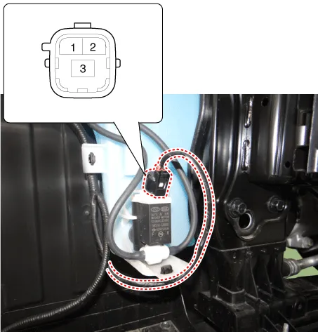
Repair procedures
| Inspection |
| 1. | With the washer motor connected to the reservoir tank, fill the reservoir tank with water.
|

| 2. | Remove the engine room under cover.
G 1.0 MPI (Refer to Engine Mechanical System - "Engine Room Under Cover")
G 1.2 MPI (Refer to Engine Mechanical System - "Engine Room Under Cover")
|
| 3. | Remove the front wheel guard [RH].
(Refer to Body - "Front Wheel Guard")
|
| 4. | Connect positive (+) battery cables to terminal 3 and negative (-) battery cables to terminal 2 respectively. |
| 5. | Check that the motor operates normally and the washer motor runs and water sprays from the front nozzles. |
| 6. | If they are abnormal, replace the washer motor. [Front & Rear washer]
|
Repair procedures Inspection Multifunction Switch Inspection 1. Check for continuity between the terminals in each switch position as shown below.
Other information:
Kia Picanto (JA) 2017-2026 Service & Repair Manual: Electro Chromic Inside Rear View Mirror
Components and components location Components Description and operation Description The ECM (Electro Chromatic inside rear view Mirror) is one that automatically dims to protect the driver’s eyes when it senses light reflecting from the car behind.
Kia Picanto (JA) 2017-2026 Service & Repair Manual: Sunroof
C
Categories
- Manuals Home
- Kia Picanto Owners Manual
- Kia Picanto Service Manual
- Charging System
- Clutch Cable
- Fuel Delivery System
- New on site
- Most important about car

Copyright © 2026 www.kpicanto.com - 0.0182