Kia Picanto (JA): Body Electrical System / Horn
Components and components location
| Component Location |
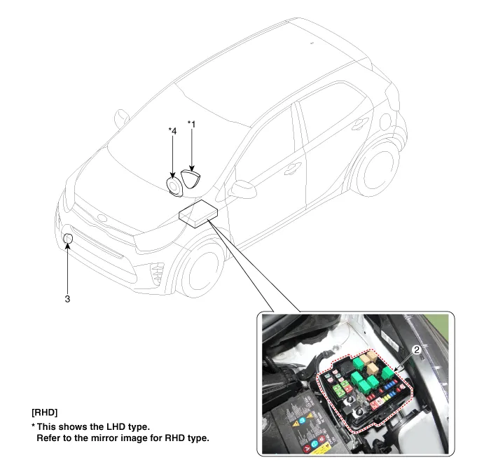
| 1. Horn switch 2. Horn relay | 3. Horn 4. Clock spring |
Repair procedures
| Removal |
| 1. | Disconnect the negative (-) battery terminal. |
| 2. | Remove the engine room under cover.
G 1.0 MPI (Refer to Engine Mechanical System - "Engine Room Under Cover")
G 1.2 MPI (Refer to Engine Mechanical System - "Engine Room Under Cover")
|
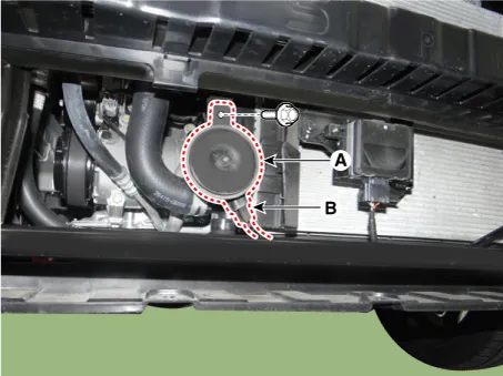
| 3. | Remove the horn (A) after disconnecting the horn connector (B) and loosening the mounting the bolt.
|
| Installation |
| 1. | Install the horn after connecting the horn connector. |
| 2. | Install the engine room under cover. |
| 3. | Connect the negative (-) battery terminal. |
| Inspection |
| 1. | The relay on the horn of this vehicle is built into the engine room relay block. |
Schematic diagrams Circuit Diagram Repair procedures Removal 1.Disconnect the negative (-) battery terminal. 2.Remove the crash pad lower panel.
Repair procedures Inspection 1.Disconnect the key warning switch connector (A) and ignition switch connector (B) from the steering column. 2.
Other information:
Kia Picanto (JA) 2017-2026 Service & Repair Manual: Headlamp Leveling Switch
Schematic diagrams Circuit Diagram Repair procedures Removal 1.Disconnect the negative (-) battery terminal. 2.Remove the crash pad lower panel. (Refer to Body - "Crash Pad Lower Panel") 3.Remove the crash pad side switch (A) after loosening the mounting screws.
Kia Picanto (JA) 2017-2026 Service & Repair Manual: Front Wiper Motor
Components and components location Component Location 1. Cap 2. Nut 3. Wiper arm & blade 4. Cowl top cover 5. Bolt 6. Wiper motor & linkage assembly 7. Wiper motor connector Repair procedures Removal 1.Disconnect the negative (-) battery terminal.
Categories
- Manuals Home
- Kia Picanto Owners Manual
- Kia Picanto Service Manual
- Charging System
- Engine Oil and Filter
- Thermostat
- New on site
- Most important about car
