
Kia Picanto (JA): Button Engine Start System / Start/Stop Button
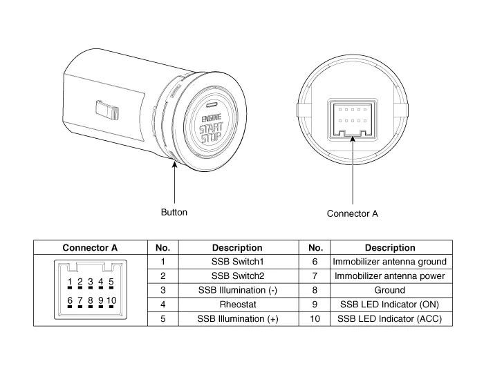
Components and components location
| Component |
Repair procedures
| Removal |
| 1. | Disconnect the negative (-) battery terminal. |
| 2. | Remove the crash pad lower panel.
(Refer to Body - "Crash Pad Lower Panel")
|
| 3. | Remove the steering column shroud lower panel.
(Refer to Body - "Steering Column Shroud Panel")
|
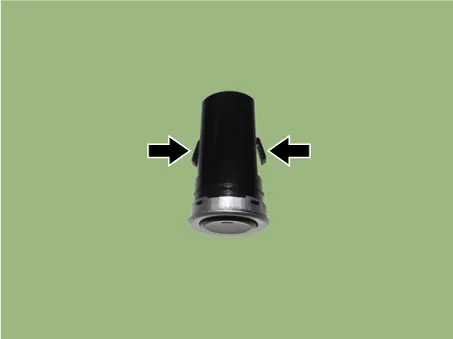
| 4. | Remove the start/stop button (A) by pushing it out from the inside with hands.
|

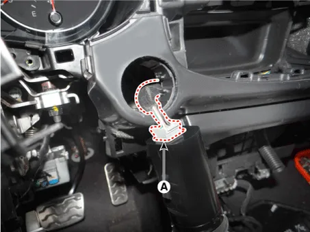
| 5. | Disconnect the start/stop button connector (A).
|
| Installation |
| 1. | Connect the start/stop button connector. |
| 2. | Install the start/stop button. |
| 3. | Install the steering column shroud lower panel. |
| 4. | Install the crash pad lower panel. |
| 5. | Connect the negative (-) battery terminal. |
Components and components location Component Location 1. Body control module (BCM) 2. Smart key unit (SMK) 3. Interior antenna 1 4. Interior antenna 2 5.
Components and components location Component Repair procedures Removal 1.Disconnect the negative(-) battery terminal. 2.Remove the crash pad lower panel.
Other information:
Kia Picanto (JA) 2017-2026 Service & Repair Manual: Headlamps
Description and operation Description BI-FUNCTION 1. Definition – A headlamp with integrated functions of high and low beam – The light is controlled by rotating the shield inserted to the lens.
Kia Picanto (JA) 2017-2026 Service & Repair Manual: Seat Heater
Components and components location Component Location 1. Seat heater unit 2. Front seat back heater 3. Front seat cushion heater Schematic diagrams Circuit Diagram Repair procedures Inspection 1.Check for continuity and measure the resistance between terminals No 1 and No 4.
Categories
- Manuals Home
- Kia Picanto Owners Manual
- Kia Picanto Service Manual
- Thermostat
- Clutch Cable
- Body Control Module (BCM)
- New on site
- Most important about car
