Kia Picanto (JA): Rear Glass Defogger / Rear Glass Defogger Printed Heater
Kia Picanto (JA) 2017-2026 Service & Repair Manual / Body Electrical System / Rear Glass Defogger / Rear Glass Defogger Printed Heater
Repair procedures
| Inspection |
|


| 1. | Turn
on the defogger switch and use a voltmeter to measure the voltage of
each heater line in the central part of the glass. If the voltmeter
indicates 6V for a conductive line, the line of the rear window is
considered to be in good condition.
|

| 2. | If a conductive line is burned out within the area between the central part and (+) terminal, the voltmeter will indicate12V.
|

| 3. | If a conductive line is burned out within the area between the central part and (-) terminal, the voltmeter will indicate 0V.
|

| 4. | To
check for open circuits, Slowly move the test lead toward the section
where open circuits seem to exist. Try to find a point where the voltage
turns to 0V. The point where the voltage has changed is the
open-circuit point.
|

| 5. | Use
an ohmmeter to measure the resistance of each heater line between a
terminal and the center of a grid line, and between the same terminal
and the center of one adjacent heater line. The section with a broken
heater line will have a resistance twice that in other sections. In the
affected section, move the test lead to a position where the resistance
sharply changes.
|

Repair Of Broken Heater Line
Prepare the following items :
| 1. | Conductive paint. |
| 2. | Paint thinner. |
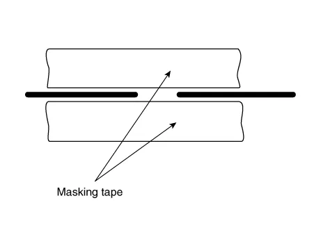
| 3. | Masking tape. |
| 4. | Silicone remover. |
| 5. | Using a thin brush : Wipe
the glass adjacent to the broken heater line, clean with silicone
remover and attach the masking tape as shown. Shake the conductive paint
container well, and apply three coats with a brush at intervals of
about 15 minutes apart. Remove the tape and allow sufficient time for
drying before applying power. For a better finish, scrape away excess
paint with a knife after the paint has completely dried. (Allow 24
hours).
|
Components and components location Component Location 1. Rear glass defogger relay 2. Rear glass defogger switch (Manual Type) 3. Rear glass defogger switch (FATC Type) 4.
Repair procedures Inspection 1.In the body electrical system, failure can be quickly diagnosed by using the vehicle diagnostic system (KDS/GDS).The diagnostic system (KDS/GDS) provides the following information.
Other information:
Kia Picanto (JA) 2017-2026 Service & Repair Manual: AVN Remote Controller
Components and components location Components 1. Left Remote Control Switch (Audio + Hands free + Voice) 2. Right Remote Control Switch (Cruise+Trip Computer) Schematic diagrams Circuit Diagram [Audio] [Audio + Bluetooth] [Audio + Bluetooth + Voice] [Trip (2 Button) + SEG LCD Cluster]
Kia Picanto (JA) 2017-2026 Service & Repair Manual: Fuses And Relays
C
Categories
- Manuals Home
- Kia Picanto Owners Manual
- Kia Picanto Service Manual
- Timing Chain
- Body Electrical System
- Cooling System
- New on site
- Most important about car

Copyright © 2026 www.kpicanto.com - 0.0204