Kia Picanto (JA): Body (Interior and Exterior) / Fender
Components and components location
| Component Location |
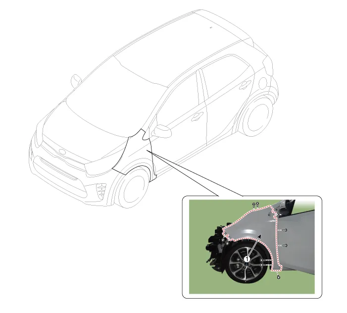
| 1. Fender assembly |
Repair procedures
| Replacement |
|

| 1. | Remove the headlamps.
(Refer to Front Bumper - "Front Bumper Assembly")
|
| 2. | Remove the front wheel guard.
(Refer to Body Side Molding - "Front Wheel Guard")
|
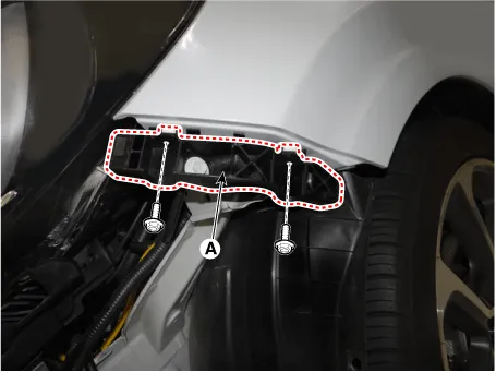
| 3. | Remove the front bumper side bracket (A) after loosening the screws.
|
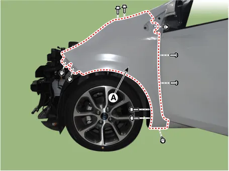
| 4. | After loosening the mounting screws, bolts, and nut, remove the fender assembly (A).
|
| 5. | Install in the reverse order of removal.
|
Components and components location Component Location 1. Crash pad center lower panel Repair procedures Replacement Put on gloves to protect your hands.
Components and components location Component Location 1. Floor carpet assembly Repair procedures Replacement Put on gloves to protect your hands.
Other information:
Kia Picanto (JA) 2017-2026 Service & Repair Manual: Smart Key Diagnostic
Repair procedures Inspection Self Diagnosis With Scan Tool It will be able to diagnose defects of SMART KEY system with KDS/GDS quickly. KDS/GDS can operates actuator forcefully, input/output value monitoring and self diagnosis. The following three features will be major problem in SMART KEY system.
Kia Picanto (JA) 2017-2026 Service & Repair Manual: Heating,Ventilation, Air Conditioning
Specifications Specification Air conditioner Item Specification Compressor Type 5VSe09(Variable Dispacement Swashplate) 5VS09 Oil type & Capacity FD46XG(PAG) 100±10g Pulley type POLY V RIBBED BEIT 6PK Displacement 90cc/rev Condenser Heat rejection 9,890 -3% kcal/h
Categories
- Manuals Home
- Kia Picanto Owners Manual
- Kia Picanto Service Manual
- Brake System
- Charging System
- Front Disc Brake
- New on site
- Most important about car
