Kia Picanto (JA): Smart Key System / Smart Key Diagnostic
Repair procedures
| Inspection |
| 1. | Problem in SMART KEY unit input. |
| 2. | Problem in SMART KEY unit. |
| 3. | Problem in SMART KEY unit output. |
| 1. | SMART KEY unit Input problem : switch diagnosis |
| 2. | SMART KEY unit problem : communication diagnosis |
| 3. | SMART KEY unit Output problem : antenna and switch output diagnosis |
| 1. | Connect the cable of KDS/GDS to the data link connector in driver side crash pad lower panel, turn the power on KDS/GDS. |
| 2. | Select the vehicle model and then SMART KEY system. |
| 3. | Select the "SMART KEY unit". |
| 4. | After IG ON, select the "Current data".
|

| 5. | You can see the situation of each switch on scanner after connecting the "current data" process.
|
| 1. | Communication diagnosis checks that the each linked components operates normal. |
| 2. | Connect the cable of KDS/GDS to the data link connector in driver side crash pad lower panel. |
| 3. | After IG ON, select the "DTC".
|

| 1. | Connect the cable of KDS/GDS to the data link connector in driver side crash pad lower panel. |
| 2. | After IG ON, select the "Actation Test".
|

| 3. | Set the smart key near the related antenna and operate it with a KDS/GDS. |
| 4. | If the LED of smart key is blinking, the smart key is normal. |
| 5. | If the LED of smart key is not blinking, check the voltage of smart key battery. |
| 6. | Antenna actuation
|
| 1. | Connect the cable of KDS/GDS to the data link connector in driver side crash pad lower panel. |
| 2. | Select the "Antenna Status Check".
|
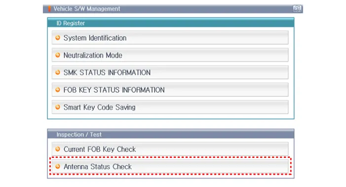
| 3. | After IG ON, select the "Antenna Status Check".
|

| 4. | Set the smart key near the related antenna and operate it with a KDS/GDS.
|

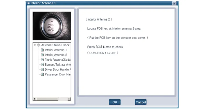
| 5. | If the smart key runs normal , the related antenna, smart key(transmission, reception) and exterior receiver are normal. |
| 6. | Antenna status
|
| 1. | Connect the cable of KDS/GDS to the data link connector in driver side crash pad lower panel. |
| 2. | After IG ON, select the "FOB KEY STATUS INFO".
|


| 1. | Connect the cable of KDS/GDS to the data link connector in driver side crash pad lower panel. |
| 2. | After IG ON, select the "SMK STATUS INFO".
|


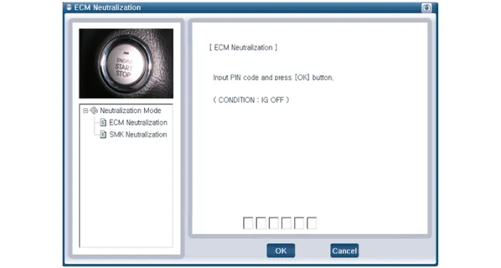
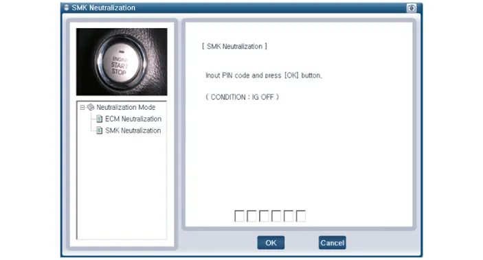
| 1. | Connect the cable of KDS/GDS to the data link connector in driver side crash pad lower panel. |
| 2. | After IG ON, select the "Neutralization mode".
|


Components and components location Components Connector Pin Information No. Connector A Connector B Connector C 1 - IGN2 Relay_output Battery (+)_Signal 2 SSB Switch1 signal_input P-CAN (Low) - 3 Driver door outside handle switch_input P-CAN (High) Immobilizer antenna (Power)_output 4 - C-CAN (High) Driver outside handle antenna (Power)_output 5 - C-CAN (Low) Passenger outside handle antenna (Power)_output 6 - SSB Amber illumination_output Bumper antenna (Power)_output 7 RPM Signal_input - Interior antenna 1 (Power)_output 8 Start signal feedback_input SSB Illumination (+)_output Interior antenna 2 (Power)_output 9 IGN2 ESCL Enable_output - 10 - Battery (+)_Power - 11 Starter relay_output IGN1 Relay_output - 12 Ground_Power1 ESCL (COM) - 13 SSB Switch2 signal_input EMS (COM) ESCL_Ground (-)_output 14 Assist door outside handle switch_input - Immobilizer antenna (Ground)_output 15 - SSB Illumination (-)_output Driver outside handle antenna (Ground)_output 16 AT : "P" Positon_input MT : Clutch switch_input SSB Illumination (Blue)_output SSB Illumination (Red)_output Passenger outside handle antenna (Ground)_output 17 ESCL Unlock switch_input - Bumper antenna (Ground)_output 18 Wheel speed sensor_input Exterior buzzer_output Interior antenna 1 (Ground)_output 19 ACC Signal_input - Interior antenna 2 (Ground)_output 20 IGN1 ESCL (+)_output - 21 Brake switch_input - 22 ACC Relay_output Ground_Power2 Schematic diagrams Circuit Diagram Repair procedures Removal Put on gloves to prevent hand injuries.
Components and components location Component Location 1. Sunroof 2. Sunroof switch 3. Sunroof motor & controller Schematic diagrams Circuit Diagram
Other information:
Kia Picanto (JA) 2017-2026 Service & Repair Manual: Power Windows
Components and components location Component Location 1. Driver power window switch 2. Assist power window switch 3. Rear power window switch 4. Front window motor 5. Rear window motor Description and operation Safety Function of Power Window When driver door power window auto-up switch is operated, safety function is acti
Kia Picanto (JA) 2017-2026 Service & Repair Manual: Temperature Control Actuator
Components and components location Component Location 1. Temerature Control Actuator Description and operation Description 1. Heater unit includes mode control actuator and temperature control actuator. 2. Temperature control actuator is located at the heater unit.
Categories
- Manuals Home
- Kia Picanto Owners Manual
- Kia Picanto Service Manual
- Clutch Cable
- Fuel Delivery System
- Engine Mechanical System
- New on site
- Most important about car
