Kia Picanto (JA): Crash Pad / Cowl Cross Bar Assembly
Components and components location
| Component Location |

| 1. Crash pad center lower panel |
Repair procedures
| Replacement |
Put on gloves to protect your hands. |

|

| 1. | Remove the main crash pad assembly.
(Refer to Crash Pad - "Main Crash Pad Assembly")
|
| 2. | Down the steering column after loosening the mounting bolts.
(Refer to Steering System - "Steering Column and Shaft")
|
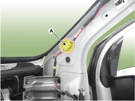
| 3. | Disconnect the connector (A) and mounting clips in the front pillar [RH].
|
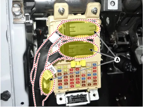
| 4. | Disconnect the passenger compartment junction box connectors (A).
|
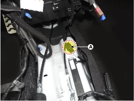
| 5. | Disconnect the smart key antenna connector (A).
|
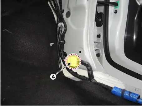
| 6. | Disconnect the passenger side wiring connector (A).
|
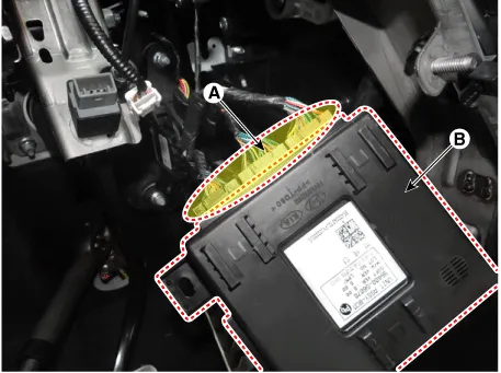
| 7. | Loosen the BCM mounting nut (A).
|

| 8. | Separate the BCM unit (B) after disconnecting the mounting nut and connectors (A).
|

| 9. | Remove the BCM unit (B) after disconnecting the connectors (A).
|
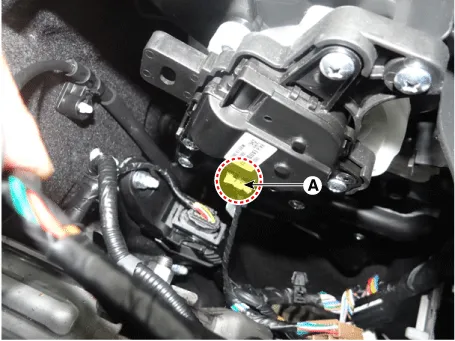
| 10. | Disconnect the mode actuator connector (A).
[Driver's]
|
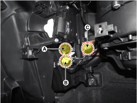
| 11. | Disconnect the temperature control actuator (A) and evaporator sensor (B) blower resistor connector (C).
|
| 12. | Disconnect the intake actuator control actuator (A).
|

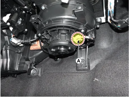
| 13. | Disconnect the blower motor connector (A), and then remove the wiring mounting clips.
|
| 14. | Disconnect the smart key unit connector after loosening the mounting nut and then remove the smart key unit (A).
|


| 15. | Remove the cap (A) and the nuts, and then remove the wiper arm (B).
|

| 16. | Disconnect the nozzle hose (A).
|

| 17. | Remove the cwol top side cover (A).
|

| 18. | Detach the clips, then remove the cowl top cover (A).
|
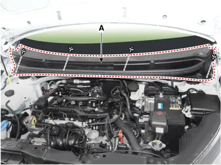
| 19. | Remove the front wiper motor (A) after loosening the mounting bolts.
|

| 20. | Disconnect the front wiper motor connector (A).
|

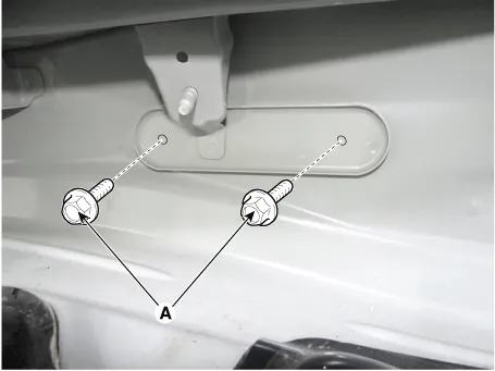
| 21. | Loosen the cowl cross bar mounting bolts (A).
|
| 22. | Remove the cowl cross bar mounting bolt caps (A).
|

| 23. | Remove the cowl cross bar assembly (A) after loosening the mounting bolts & nuts.
[Driver Side]
[Passenger Side]
|
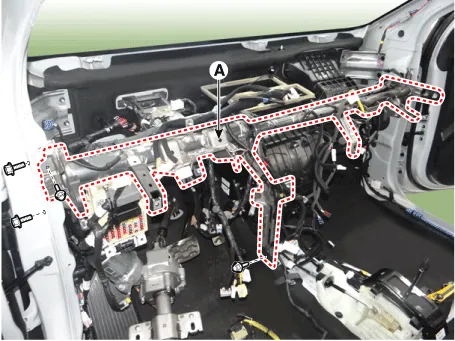

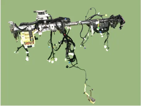
| 24. | Remove the main wiring harness (A) from the cowl cross bar.
|
| 25. | Install in the reverse order of removal.
|
Components and components location Component Location 1. Crash pad center lower panel Repair procedures Replacement Put on gloves to protect your hands.
Components and components location Component Location 1. Fender assembly Repair procedures Replacement • Be careful not to damage the fender and body.
Other information:
Kia Picanto (JA) 2017-2026 Service & Repair Manual: Junction Box (Passenger Compartment)
Components and components location Component Location I/P Junction Box Circuit (I/P Junction Box) Description and operation Description Communication Network Diagram Abbreviation Explanation ABS Anti-lock Brake System ACU Airbag Control Un
Kia Picanto (JA) 2017-2026 Service & Repair Manual: Windshield Wiper/Washer
Components and components location Component Location 1. Windshield wiper arm & blade 2. Wiper & washer switch 3. Windshield washer hose & nozzle 4. Wiper motor & linkage assembly 5. Washer motor 6. Washer reservoir tank 7. Wiper/Washer relay 8.
Categories
- Manuals Home
- Kia Picanto Owners Manual
- Kia Picanto Service Manual
- To set cruise control speed
- Engine Control / Fuel System
- Clutch Cable
- New on site
- Most important about car
