Kia Picanto (JA): Your vehicle at a glance / Engine compartment
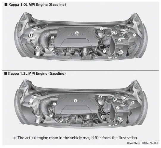
1. Engine coolant reservoir
2. Engine oil filler cap
3. Brake / clutch fluid reservoir
4. Air cleaner
5. Fuse box
6. Negative battery terminal
7. Positive battery terminal
8. Engine oil dipstick
9. Radiator cap
10. Windshield washer fluid reservoir
11. Automatic transaxle fluid dipstick
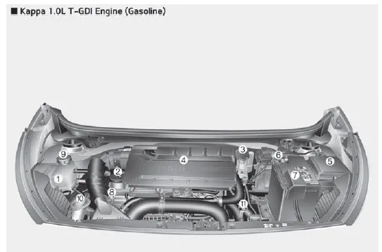
1. Engine coolant reservoir
2. Engine oil filler cap
3. Brake / clutch fluid reservoir
4. Air cleaner
5. Fuse box
6. Negative battery terminal
7. Positive battery terminal
8. Engine oil dipstick
9. Radiator cap
10. Windshield washer fluid reservoir
11. Automatic transaxle fluid dipstick
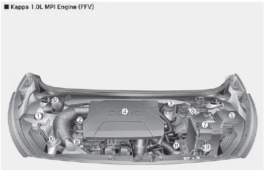
1. Engine coolant reservoir
2. Engine oil filler cap
3. Brake / clutch fluid reservoir
4. Air cleaner
5. Fuse box
6. Negative battery terminal
7. Positive battery terminal
8. Engine oil dipstick
9. Radiator cap
10. Windshield washer fluid reservoir
11. Automatic transaxle fluid dipstick
12. Gasoline reservoir
1. Instrument cluster 2. Horn 3. Driver’s front air bag 4. Light control/Turn signals 5. Wiper/Washer 6. Ignition switch ENGINE START/STOP button 7.
Other information:
Kia Picanto (JA) 2017-2026 Service & Repair Manual: Rear Glass Defogger Printed Heater
Repair procedures Inspection • Wrap tin foil around the end of the voltmeter test lead to prevent damaging the heater line. Apply pressure on the tin foil with hand and move the tin foil along the grid line to check for open circuits.
Kia Picanto (JA) 2017-2026 Service & Repair Manual: Sunroof Motor
Repair procedures Inspection 1.Disconnect the negative (-) battery terminal. 2.Remove the roof trim assembly. (Refer to Body - "Roof Trim Assembly") 3.Remove the glass motor (A) after loosening the mounting screws. 4.
Categories
- Manuals Home
- Kia Picanto Owners Manual
- Kia Picanto Service Manual
- Cooling System
- Front Disc Brake
- Clutch Cable
- New on site
- Most important about car
