Kia Picanto (JA): Your vehicle at a glance / Instrument panel overview
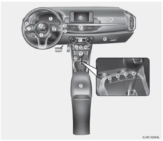
1. Instrument cluster
2. Horn
3. Driver’s front air bag
4. Light control/Turn signals
5. Wiper/Washer
6. Ignition switch
ENGINE START/STOP button
7. Steering wheel audio control
8. LCD window control
Cruise control
Speed limit control
9. Hazard warning flasher switch
10. Audio
11. Manual climate control system
Automatic climate control system
12. Cigarette lighter
13. AUX, USB port
14. Power outlet
15. Passenger’s front air bag
16. Glove box
17. Shift lever M/T
18. Seat warmer
19. Heated steering wheel switch
20. ISG (Idle Stop and Go) button
21. Center console storage
22. Cup holder
1. Inside door handle 2. Door lock/unlock button 3. Outside rearview mirror folding switch 4. Outside rearview mirror control switch 5. Central door lock switch 6.
1. Engine coolant reservoir 2. Engine oil filler cap 3. Brake / clutch fluid reservoir 4. Air cleaner 5. Fuse box 6. Negative battery terminal 7.
Other information:
Kia Picanto (JA) 2017-2026 Service & Repair Manual: Emergency Call (eCall) Unit
Components and components location Component The eCall unit for AVN is equipped in AVN head unit. Repair procedures Removal Carry out the Test Mode in the following cases.– Replacing the eCall unit– Replacing the Bac
Kia Picanto (JA) 2017-2026 Service & Repair Manual: Power Window Switch
Components and components location Components Driver Power Window Switch Connector Pin Information [All Manual / Auto Down Type] (LHD) No. Description No.
Categories
- Manuals Home
- Kia Picanto Owners Manual
- Kia Picanto Service Manual
- Thermostat
- Suspension System
- Normal Condition
- New on site
- Most important about car
